Embroidery process imitating device of computerized flat knitting machine

A computerized flat knitting and process technology, applied in textiles and papermaking, weft knitting, knitting and other directions, can solve the problems of easy adhesion of fluff and yarn flocs, affecting the sliding of the machine head, and troublesome cleaning, so as to improve the quality of textiles and reduce The effect of tangle and broken ends, reducing the number of downtimes

Active Publication Date: 2021-08-24
南通喜丹奴纺织品有限公司
View PDF6 Cites 0 Cited by
  • Summary
  • Abstract
  • Description
  • Claims
  • Application Information

AI Technical Summary

Problems solved by technology

[0002] When the computerized flat knitting machine is used to imitate the embroidery process for production, the yarn is directly threaded, and the yarn is not processed before knitting, which is prone to defective products such as thread breakage. At the same time, during the computerized flat knitting machine, the workshop There will be a lot of fluff and yarn in the slide rail, because the slide rail contains lubricating oil, it is easy to adhere to the fluff and yarn, long-term accumulation will affect the sliding of the machine head, and it is more troublesome to clean. Therefore, a computerized flat knitting machine is needed. installation imitating the embroidery process

Method used


Image

  • Embroidery process imitating device of computerized flat knitting machine
  • Embroidery process imitating device of computerized flat knitting machine
  • Embroidery process imitating device of computerized flat knitting machine

Examples


Embodiment Construction

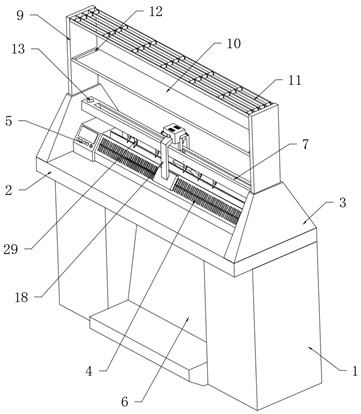
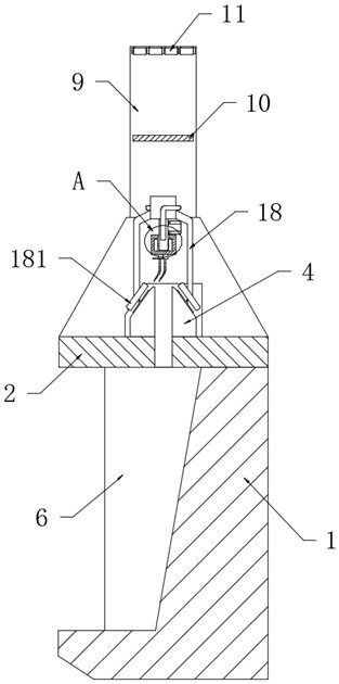
[0024] refer to figure 1 , a computerized flat knitting machine imitating the embroidery process device, comprising a machine base 1, the machine base 1 is fixedly connected with an operating table 2, both ends of the operating table 2 are fixedly connected with a frame 3, and the upper table of the operating table 2 is located on two A textile mechanism 4 is installed between the brackets of the frame 3, a controller 5 is installed at a position close to the frame 3 on one side of the console 2, and a slide bar 7 is fixedly connected to the upper ends of the two frame 3, and the slide bar 7 There is a machine head control device on the top, and the upper end surfaces of the two frames 3 are fixedly connected with a support plate 9, and the middle positions of the two support plates 9 are jointly fixedly connected with a horizontal yarn swing plate 10 for placing yarn required for weaving. Yarn bobbins, the upper ends of the two support plates 9 are jointly provided with a wir...


PUM


Abstract

The invention discloses an embroidery process imitating device of a computerized flat knitting machine. The device comprises a machine base; an operation table is fixedly connected to the machine base; the two ends of the operation table are both fixedly connected with racks; a spinning mechanism is installed at the position, between two rack supports, of the table top of the operation table; a controller is installed at the position, close to the rack on one side, of the table top of the operation table; the upper ends of the two racks are jointly and fixedly connected with a sliding rod; and a machine head control device is arranged on the sliding rod. According to the device, when a machine head moves, yarn wadding and fluff in a sliding rail can be automatically sucked into a cleaning box to be cleaned, so that it is avoided that the yarn wadding and the fluff are accumulated in the sliding rail to affect movement of the machine head; and yarn can be waxed, so that yarn hairiness can be attached, the yarn entanglement and end breakage rate is reduced, meanwhile, the lubricating effect on the spinning mechanism is achieved, the shutdown frequency is reduced, and the quality of textiles produced by the computerized flat knitting machine is further improved.

Description

technical field [0001] The invention relates to the technical field of knitting machines, in particular to a device for computerized flat knitting machines imitating embroidery techniques. Background technique [0002] When the computerized flat knitting machine is used to imitate the embroidery process for production, the yarn is directly threaded, and the yarn is not processed before knitting, which is prone to defective products such as thread breakage. At the same time, during the computerized flat knitting machine, the workshop There will be a lot of fluff and yarn wadding in the slide rail. Because the slide rail contains lubricating oil, it is easy to adhere to the fluff and wadding. Long-term accumulation will affect the sliding of the machine head, and it is troublesome to clean. Therefore, a computerized flat knitting machine is needed. A device that imitates the craft of embroidery. Contents of the invention [0003] The purpose of the present invention is to s...

Claims


Application Information

Patent Timeline
IPC IPC(8): D04B15/96D04B35/32D04B35/24D04B15/38D04B35/28
CPCD04B15/38D04B15/96D04B35/24D04B35/28D04B35/32
Inventor 洪昌马
Owner 南通喜丹奴纺织品有限公司
Why Eureka
Try Eureka