Eureka AIR delivers breakthrough ideas for toughest innovation challenges, trusted by R&D personnel around the world.

Flexible clamping device and method for turning thin-wall deep-cylinder stretching part

A flexible clamping and part technology, applied in the field of machining, can solve the problems of easy deformation of the inner cavity of the part and affecting the machining accuracy.

Active Publication Date: 2021-08-27
重庆伊洛美克动力总成有限公司
View PDF6 Cites 1 Cited by
  • Summary
  • Abstract
  • Description
  • Claims
  • Application Information

AI Technical Summary

Problems solved by technology

[0003]The purpose of the present invention is to provide a thin-walled deep-tube drawing part turning flexible clamping device and method, aiming at solving the problem of the deformation caused by the internal support form in the prior art. When processing larger parts, the inner cavity of the part is prone to deformation during the clamping process, which affects the technical problems of machining accuracy

Method used


Image

  • Flexible clamping device and method for turning thin-wall deep-cylinder stretching part
  • Flexible clamping device and method for turning thin-wall deep-cylinder stretching part
  • Flexible clamping device and method for turning thin-wall deep-cylinder stretching part

Examples


Embodiment Construction

[0023] Embodiments of the present invention are described in detail below, examples of which are shown in the drawings, wherein the same or similar reference numerals designate the same or similar elements or elements having the same or similar functions throughout. The embodiments described below by referring to the figures are exemplary and are intended to explain the present invention and should not be construed as limiting the present invention.

[0024] In describing the present invention, it should be understood that the terms "length", "width", "upper", "lower", "front", "rear", "left", "right", "vertical", The orientation or positional relationship indicated by "horizontal", "top", "bottom", "inner", "outer", etc. are based on the orientation or positional relationship shown in the drawings, and are only for the convenience of describing the present invention and simplifying the description, rather than Nothing indicating or implying that a referenced device or element...


PUM


Abstract

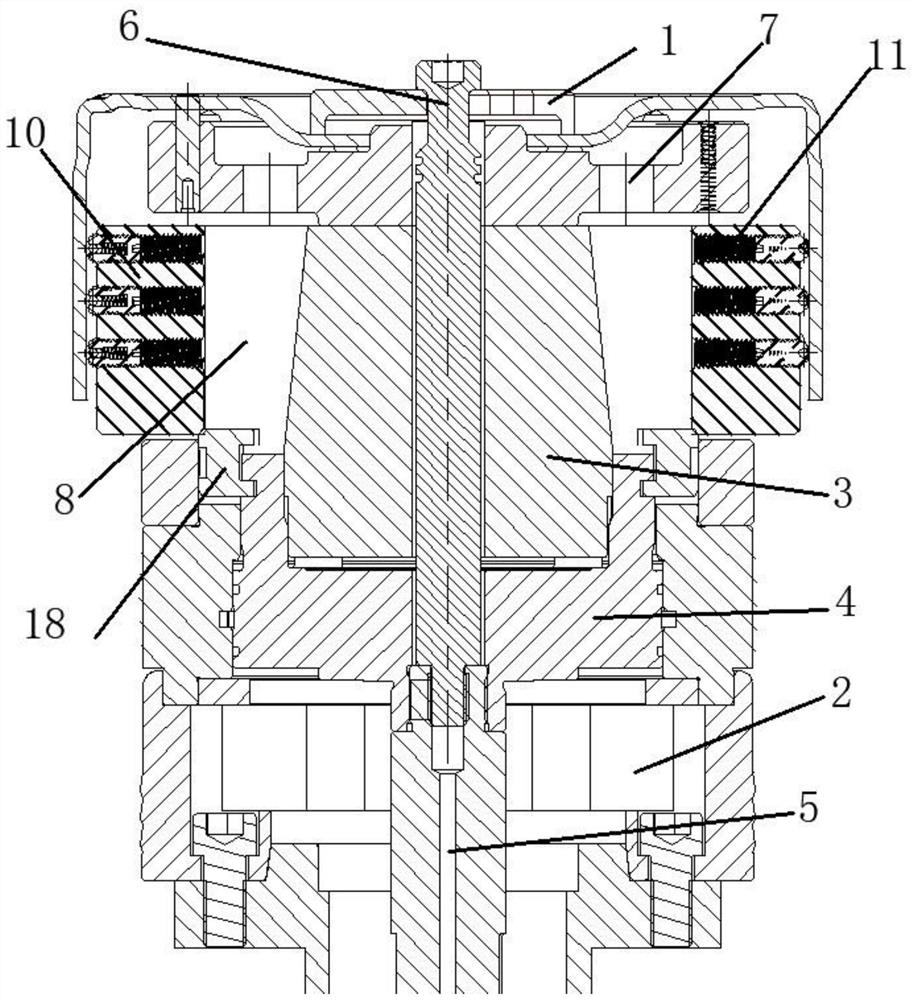
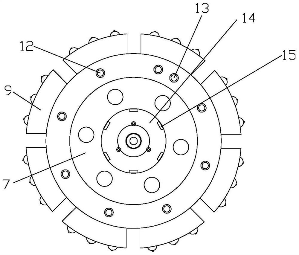
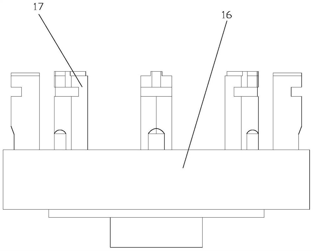
The invention discloses a flexible clamping device and method for turning a thin-wall deep-cylinder stretching part. A main shaft pull rod is movably connected with a flange plate and located in a movable hole, a pressing plate pull rod is fixedly connected with the main shaft pull rod and located above the main shaft pull rod, and a pull claw is detachably connected with the pressing plate pull rod and located between a guide cone and the flange plate. A basic expansion block is movably connected with the guide cone and installed on the outer side wall of the guide cone, the basic expansion block is clamped with the pull claw and located above the pull claw, each plunger expansion block is fixedly connected with the basic expansion block, and the plunger expansion blocks are uniformly distributed on the outer side wall of the basic expansion block at interval. By means of the structure, the principle that single power drives double mechanisms to move at the same time and the characteristic of flexible change of ball plungers are utilized, turning after stable clamping of the thin-wall deep-cylinder stretching part is guaranteed, and therefore parts with large deformation can be machined.

Description

technical field [0001] The invention relates to the technical field of mechanical processing, in particular to a flexible clamping device and method for turning thin-walled deep tube drawing parts. Background technique [0002] When processing thin-walled deep-tube drawing parts, there are dual problems of stress concentration and stress release in thin-walled deep-tube drawing parts. The outer wall turning fixture mainly has two clamping methods. First, ordinary three-jaw clamping of the outer circle; second, inner To support the inner circle of the part, both clamping methods require that the part will not deform or have a small amount of deformation during the clamping process to ensure that the size of the part is stable after processing. At present, the popular clamping method at home and abroad is to use the second clamping method , through the form of inner support to stably clamp parts with relatively high rigidity for processing, but for parts with large deformation...

Claims


Application Information

Patent Timeline
Patent Type & Authority Applications(China)
IPC IPC(8): B23B5/00B23B25/06B23Q3/14
CPCB23B5/00B23B25/06B23Q3/14
Inventor 肖奇李华乔
Owner 重庆伊洛美克动力总成有限公司
Why Eureka
Eureka Blog
Learn More