Floating type offshore wind turbine system

An offshore fan and floating technology, which is applied in wind power generation, floating buildings, ships, etc., can solve the problems of insufficient ballast in the lower part of the water, the center of gravity of the platform is moved up, and the area is limited, so as to improve the effect of ballast weight gain. , the effect of increasing the recovery stiffness and lowering the center of gravity

Inactive Publication Date: 2021-08-27
CHINA ENERGY ENG GRP GUANGDONG ELECTRIC POWER DESIGN INST CO LTD
View PDF9 Cites 3 Cited by
  • Summary
  • Abstract
  • Description
  • Claims
  • Application Information

AI Technical Summary

Problems solved by technology

[0006] In order to solve the above problems, the purpose of the present invention is to provide a floating offshore wind turbine system to solve the problem of the existing new semi-submersible floating offshore wind power platform after the three floating tanks in the upper part of the peripheral water are close to the water surface. The center of gravity of the platform moves upwards, reducing the overall stability of the platform; moreover, a truss structure is used to connect the peripheral pontoon and the middle pontoon. On the one hand, the structural strength here is difficult to meet the safety requirements. On the other hand, the underwater upper Insufficient buoyancy is not conducive to raising the buoyancy center, and the ballast in the lower part of the water is not large enough, which is not conducive to the lowering of the center of gravity; in addition, although the damping plate is installed, due to the limited area of ​​the damping plate, it is closer to the sea surface and other factors. , can not significantly improve the heaving motion performance of the floating wind power platform

Method used


Image

  • Floating type offshore wind turbine system
  • Floating type offshore wind turbine system
  • Floating type offshore wind turbine system

Examples


Embodiment Construction

[0046] The specific implementation manners of the present invention will be further described in detail below in conjunction with the accompanying drawings and embodiments. The following examples are used to illustrate the present invention, but are not intended to limit the scope of the present invention.

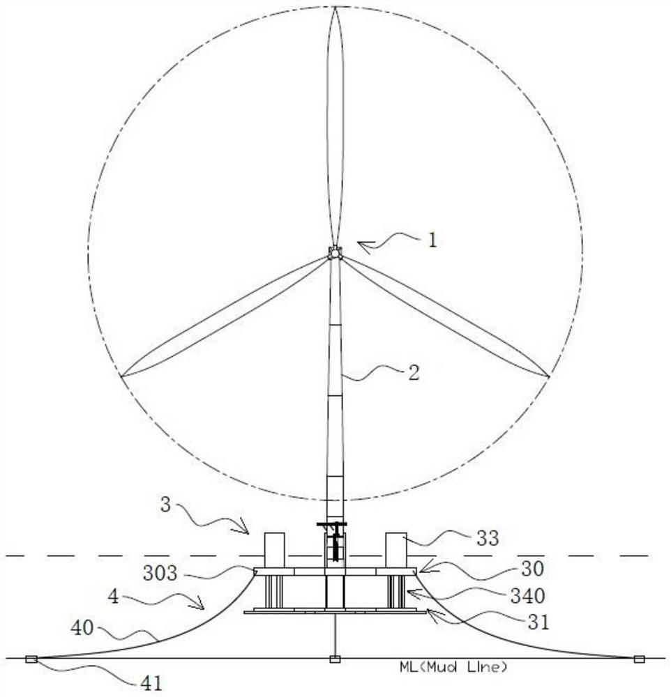
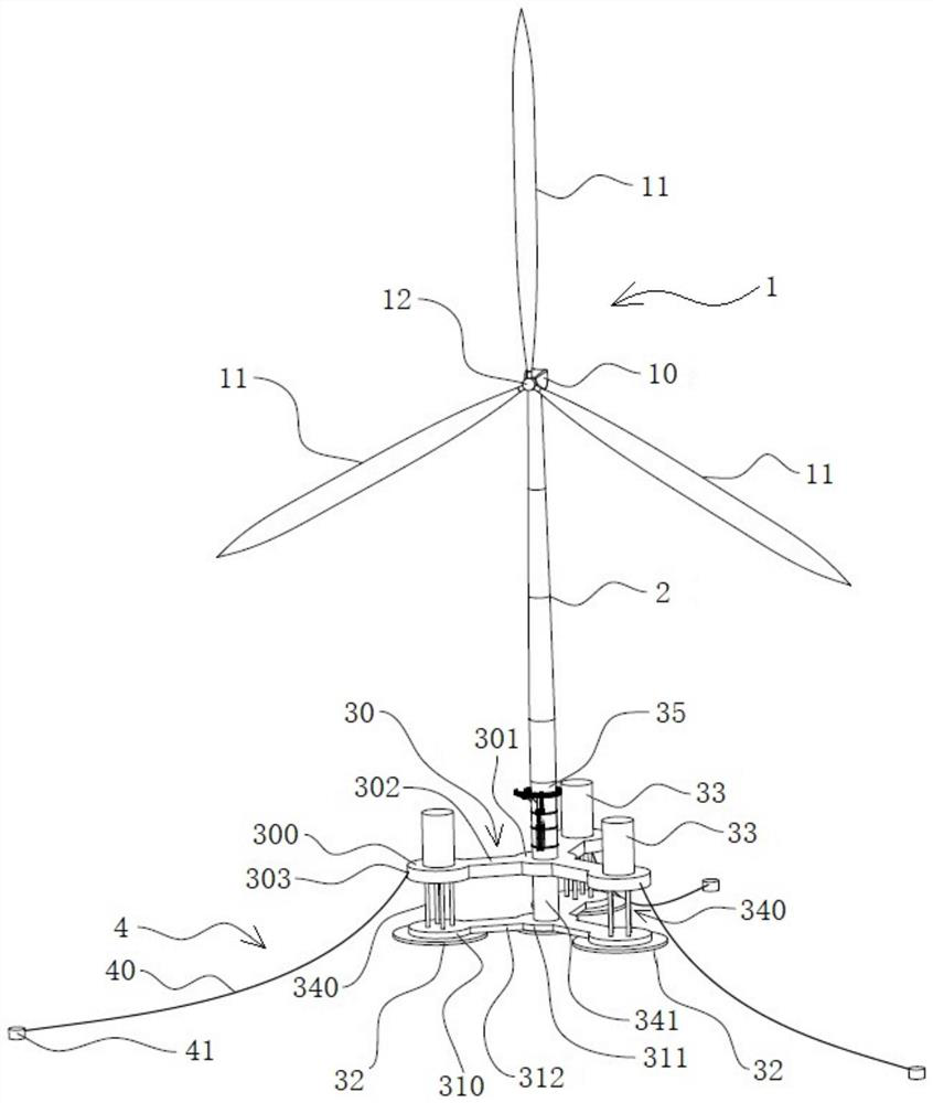
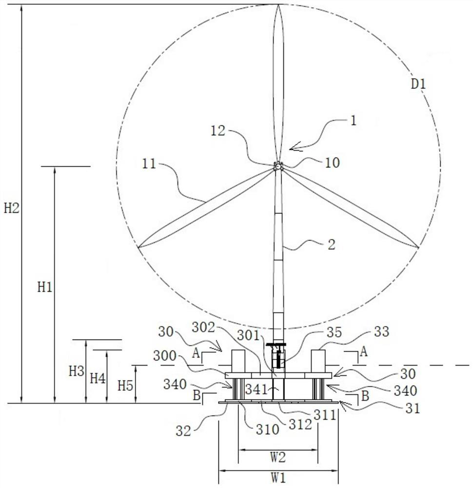
[0047] Specific embodiment 1 of the floating offshore wind turbine system of the present invention, such as Figure 1 to Figure 8 As shown, the floating offshore wind turbine system includes a wind turbine 1, a tower 2, a floating platform 3 and an anchoring system 4. The wind turbine 1 is installed on the upper end of the tower 2, and the lower part of the tower 2 is fixed on the floating platform 3. The mooring system 4 is connected to the floating platform 3, the floating platform 3 includes a buoyancy module 30 and a ballast module 31, the ballast module 31 is arranged on the lower side of the buoyancy module 30; the buoyancy module 30 includes a central buoyancy modul...


PUM


Abstract

The invention provides a floating type offshore wind turbine system, and relates to the field of offshore wind turbines. The floating type offshore wind turbine system comprises a wind turbine generator set, a tower drum, a floating type platform and an anchoring system. The floating type platform comprises a buoyancy tank assembly and a ballast tank assembly arranged on the lower side of the buoyancy tank assembly. The buoyancy tank assembly comprises a central buoyancy tank, at least three corner point buoyancy tanks which are distributed at intervals in the circumferential direction and a connecting buoyancy tank, the ballast tank assembly comprises a central ballast tank, at least three corner point ballast tanks which are distributed at intervals in the circumferential direction and a connecting ballast tank; the buoyancy tank and the ballast tank are connected through a truss type round pipe or a cylindrical structure, and a fixed ballast body is further arranged on the lower portion of each corner point ballast tank. The buoyancy tank assembly provides large buoyancy to improve the buoyancy center, and the bottom large-area ballast tank assembly and the fixed ballast body lower the gravity center, so that the gravity center of the whole structure system is lower than the buoyancy center, the still water deflection recovery rigidity is effectively increased, and the stability and the movement performance of the floating type wind turbine system are improved.

Description

technical field [0001] The invention relates to the technical field of offshore wind turbines, in particular to a floating offshore wind turbine system. Background technique [0002] Offshore wind farms are green energy projects that use offshore wind energy to generate electricity. According to the sea area, they are divided into shallow sea wind farms and deep sea wind farms. The latter uses floating wind turbine foundations, which are fixed to the seabed through mooring systems. The construction cost is low and the power generation efficiency is low. high. [0003] For example, the Chinese utility model patent with the authorized announcement number CN203419250U and the authorized announcement date of 2014.02.05 discloses a new type of semi-submersible floating offshore wind power platform, and specifically discloses the supporting superstructure of the semi-submersible floating offshore wind power platform Including blades, hubs, towers and nacelles; the floating platfo...

Claims


Application Information

Patent Timeline
Patent Type & Authority Applications(China)
IPC IPC(8): B63B35/44B63B39/02B63B39/03
CPCB63B35/44B63B39/02B63B39/03B63B2035/446Y02E10/727
Inventor 杨敏冬何小华马兆荣刘东华任灏王洪庆林耀森
Owner CHINA ENERGY ENG GRP GUANGDONG ELECTRIC POWER DESIGN INST CO LTD
Why Eureka
Try Eureka