
Floating power generation system utilizing ocean wave energy

A power generation system and wave energy technology, which is applied to ocean energy power generation, engine components, machines/engines, etc., can solve the problems of large movement drop of the first rack, small drop of the first rack, and increased utilization of huge wave energy. , to achieve the effect of high energy utilization

Pending Publication Date: 2021-08-27
海南电网有限责任公司三沙供电局
View PDF0 Cites 1 Cited by
  • Summary
  • Abstract
  • Description
  • Claims
  • Application Information

AI Technical Summary

Problems solved by technology

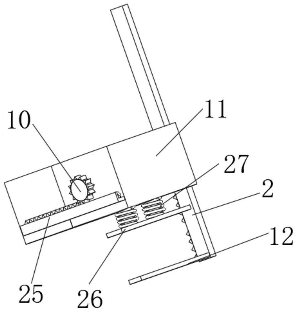
[0004] The purpose of this application is to provide a floating power generation system using ocean wave energy to solve the problem that some power generation devices proposed in the background technology have low energy utilization rates for some huge waves. The present invention uses the second power generation mechanism The cutting board is equipped with an idle ring, so that when the wave is small, the first rack moves with the floating mechanism and the drop is small. At this time, the control plate at the bottom of the first rack moves in the inner cavity of the idle ring and cannot move the idle ring. , at this time, only the first power generating mechanism generates power. When the waves are huge, the force of the upward movement of the first rack by the floating mechanism is large enough and the movement of the first rack has a large drop. At this time, the first rack moves to make the first rack The rotation of the gear makes the first power generation mechanism generate electricity, and at the same time, the control plate at the bottom of the first rack moves upwards, causing the lost motion ring to move upward. At this time, the second power generation mechanism also generates electricity, so that the energy utilization rate of huge waves becomes higher.

Method used


Image

  • Floating power generation system utilizing ocean wave energy
  • Floating power generation system utilizing ocean wave energy
  • Floating power generation system utilizing ocean wave energy

Examples


Embodiment

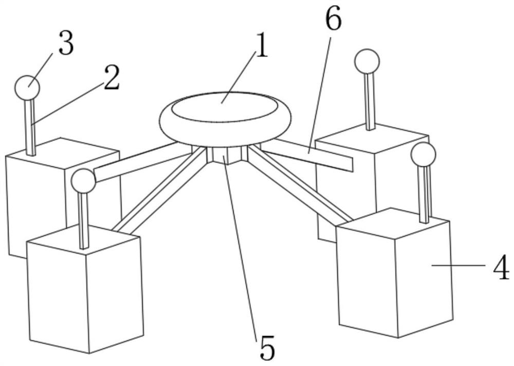
[0042] Example: Reference Figure 1-8 A floating power generation system using ocean wave energy is shown, including a floating airbag 1, a core control box 5 is installed at the bottom of the floating airbag 1, and the floating airbag 1 is any one in the prior art.

[0043] The four sides of the core control box 5 are all equipped with connecting rods 6, and the ends of the four connecting rods 6 away from the core control box 5 are all equipped with a power generation box 4, and the four sides of the core control box 5 are provided with a power generation box 4 by setting four connecting rods 6 , high power generation efficiency.

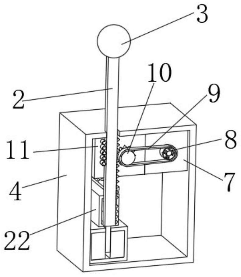
[0044] The inboard of generating box 4 is equipped with the first generating mechanism, and installing block 11 is installed in generating box 4 inboards, and the first gear 10 is installed with rotation on installing block 11, and first gear 10 is connected with the first generating mechanism by transmission mechanism, the first One side of the ge...


PUM


Abstract

The invention discloses a floating power generation system utilizing ocean wave energy, and relates to the technical field of wave power generation. The floating power generation system comprises a floating air bag, a core control box is installed at the bottom end of the floating air bag, connecting rods are installed on the four sides of the core control box, power generation boxes are installed at the ends, away from the core control box, of the four connecting rods, and a first power generation mechanism is installed on the inner side of each power generation box. The first power generation mechanisms and second power generation mechanisms are arranged, when waves are huge, the upward moving force of a floating mechanism on a first rack is large enough, the vertical moving fall of the first rack is large, the first rack moves to enable a first gear to rotate to enable the first power generation mechanisms to generate power, and meanwhile, a control plate at the bottom end of the first rack moves upwards, an idle stroke ring moves upwards, and at the moment, the second power generation mechanisms also generate power, so that the energy utilization rate of the huge waves is increased.

Description

technical field [0001] The present invention relates to the technical field of wave energy power generation, in particular to a floating power generation system utilizing ocean wave energy. Background technique [0002] Wave energy is one of the most abundant energy sources in ocean energy, and it is also the ocean energy that has been studied most recently in ocean energy utilization research. Its development and utilization technology has matured and is entering or approaching the stage of commercial development. The development of marine resources in coastal areas and the development of islands far away from the mainland are of great significance. [0003] In the prior art, the floating power generation system using ocean wave energy relies on the energy of ocean waves to drive the floating parts to move up and down to generate electricity for related components. However, the wave energy that this power generation device can use is not much. Not high, so a floating power...

Claims


Application Information

Patent Timeline
Patent Type & Authority Applications(China)
IPC IPC(8): F03B13/16
CPCF03B13/16F05B2220/706Y02E10/30
Inventor 吴清吴祝李王敬春高玉洁洪同庆禹鹏陈益华邢涛张小店冯乃华赵景飞陈彬周杰符礼攀陈运钦吴清川王绥余刘获张渊羊冠宝蔡儒宁万全曾扬骋
Owner 海南电网有限责任公司三沙供电局
Learn More