Induction heating high-temperature oil vapor collecting and discharging device

An induction heating and discharge device technology, applied in the field of metal tube heating, can solve the problems of time-consuming and laborious induction heating box components, damage, incomplete treatment, etc., to solve the collection and discharge problems, prolong the service life, and ensure the heat treatment effect. Effect

Active Publication Date: 2021-08-27
BAODING SIFANGSANYI ELECTRIC +2
View PDF9 Cites 0 Cited by
  • Summary
  • Abstract
  • Description
  • Claims
  • Application Information

AI Technical Summary

Problems solved by technology

There are two most common discharge methods now. The first is to let the high-temperature oil vapor condense in the induction heating box and then clean it regularly. Because the oil condenses for too long, the oil will become extremely viscous and it is very difficult to clean it up; the second is High-temperature oil vapor is directly discharged into the air, and then sucked away by a high-power smoking machine for centralized treatment
[0004] The first method is time-consuming and labor-intensive and may cause damage to the devices in the induction heating box. The second method is not thorough and may cause greater pollution to the environment.

Method used


Image

  • Induction heating high-temperature oil vapor collecting and discharging device
  • Induction heating high-temperature oil vapor collecting and discharging device
  • Induction heating high-temperature oil vapor collecting and discharging device

Examples


Embodiment Construction

[0024] The following will clearly and completely describe the technical solutions in the embodiments of the present invention with reference to the accompanying drawings in the embodiments of the present invention. Obviously, the described embodiments are only some, not all, embodiments of the present invention. Based on the embodiments of the present invention, all other embodiments obtained by persons of ordinary skill in the art without making creative efforts belong to the protection scope of the present invention.

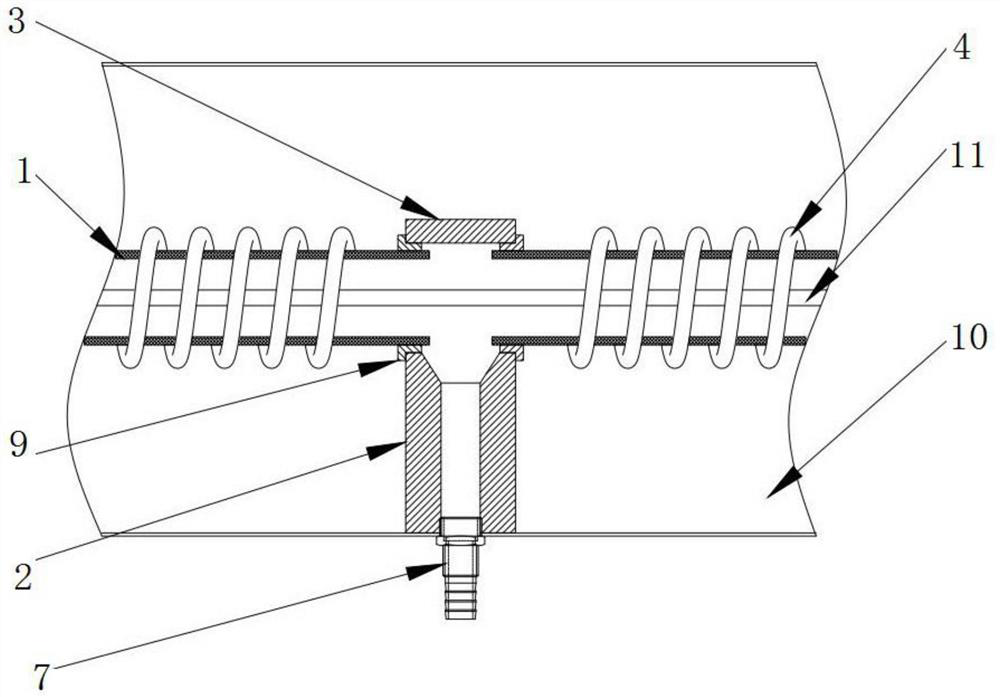
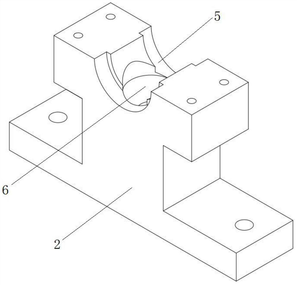
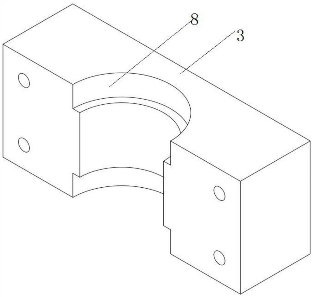
[0025] The embodiment of the present invention discloses an induction heating high-temperature oil vapor collection and discharge device, which includes a porcelain tube 1, a porcelain tube support 2, a porcelain tube support cover 3, and an induction coil 4, wherein the induction coil 4 surrounds the outer wall of the porcelain tube 1 ; Both sides of the top of the porcelain tube support 2 are provided with a lower half-ring groove 5, and the middle of the por...


PUM


Abstract

The invention discloses an induction heating high-temperature oil vapor collecting and discharging device. An induction coil surrounds the outer wall of a porcelain tube; lower semi-ring grooves are formed in the two sides of the top of a porcelain tube support, a penetrating oil discharging channel is formed in the middle of the porcelain tube support, and an oil discharging nozzle is mounted at the bottom end of the oil discharging channel; upper semi-ring grooves matched with the lower semi-ring grooves are formed in the two sides of the bottom of a porcelain tube support upper cover, the porcelain tube support upper cover is mounted on the top of the porcelain tube support, the upper semi-ring grooves and the lower semi-ring grooves are matched to form tube opening grooves, and tube openings of the porcelain tubes located on the two sides of the porcelain tube support are installed in the tube opening grooves. Oil vapor is collected through the closed porcelain tube, the oil vapor is condensed into liquid in the porcelain tube after encountering the porcelain tube with the lower temperature; at the same time, due to the fact that the oil liquid is close to a metal tube in the porcelain tube, a high-temperature metal tube provides a certain temperature for the oil liquid, so that the liquidity of the oil liquid is guaranteed; and the induction heating high-temperature oil vapor collecting and discharging device is good in sealing performance, simple in structure, small in size, low in cost, and convenient to mount and maintain.

Description

technical field [0001] The invention relates to the technical field of metal tube heating, in particular to an induction heating high-temperature oil vapor collection and discharge device. Background technique [0002] In the induction heating industry, especially during the induction heating process of metal pipes, the residual oil on the metal pipes is heated and vaporized, producing a large amount of high-temperature oil vapor, which condenses to form viscous oil stains, which seriously affects the metal pipes. Heat treatment effect, while causing pollution of the induction heating box and damage to important components. [0003] In the common copper tube annealing process, a large amount of high-temperature oil vapor will be generated when the copper tube is heated by induction. The oil vapor comes from the residual oil when the copper tube is drawn, and the oil vaporizes when heated. There are two most common discharge methods now. The first is to let the high-temperat...

Claims


Application Information

Patent Timeline
IPC IPC(8): F16L55/07F16L45/00F16L53/34F16L3/10F16L41/02F16L41/12
CPCF16L55/07F16L45/00F16L53/34F16L3/1091F16L41/021F16L41/12F16L41/088F16L41/086Y02P10/25
Inventor 李威常丽凯王九刚杨占勋崔改冰郭晓旺李建华张建清郑祺高海鹏张明理
Owner BAODING SIFANGSANYI ELECTRIC
Why Eureka
Try Eureka