Detection equipment and detection method

A technology of detection equipment and detection platform, which is applied in the direction of offensive equipment, weapon accessories, fuzes, etc., can solve the problems of inconvenient use, low integration, open circuit, etc., and achieve the effect of convenient use

Pending Publication Date: 2021-08-27
BEIJING QAML OF SCI & TECH CO LTD
View PDF9 Cites 0 Cited by
  • Summary
  • Abstract
  • Description
  • Claims
  • Application Information

AI Technical Summary

Problems solved by technology

[0002] The inherent advantages of electronic detonators such as safety, reliability, precision, and environmental protection have been widely recognized and used in the blasting industry. With the increase in the output of electronic detonators, the existing production and testing methods for control modules of electronic detonators It is more and more unsuitable to meet the current needs. The existing electronic detonator control module test equipment has complex structure and low integration. It is difficult to quickly achieve the desired effect by crimping the detection end of the electronic detonator control module during testing. The electronic detonator control module It is easy to contact abnormalities (such as open circuit, short circuit, etc.) between the detection terminal and the equipment, resulting in low production efficiency, inconvenient use, high maintenance costs, etc., and difficult transportation is not conducive to market transactions. During the test, the phenomenon of martyrdom between the charge heads of adjacent electronic detonator control modules is prone to occur, which increases the loss of electronic detonator control module products and increases production costs while the production efficiency is low.
It can be seen that the current testing equipment can no longer meet the high-production testing requirements of the electronic detonator control module, and then cooperate with the quality control platform to solve the problems that the current production data of the electronic detonator control module cannot be statistically collected, and quality control analysis and tracking cannot be performed.

Method used


Image

  • Detection equipment and detection method
  • Detection equipment and detection method
  • Detection equipment and detection method

Examples


Embodiment Construction

[0062] Exemplary embodiments of the present disclosure will be described in more detail below with reference to the accompanying drawings. Although exemplary embodiments of the present disclosure are shown in the drawings, it should be understood that the present disclosure may be embodied in various forms and should not be limited by the embodiments set forth herein. Rather, these embodiments are provided for more thorough understanding of the present disclosure and to fully convey the scope of the present disclosure to those skilled in the art.

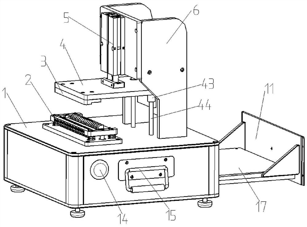
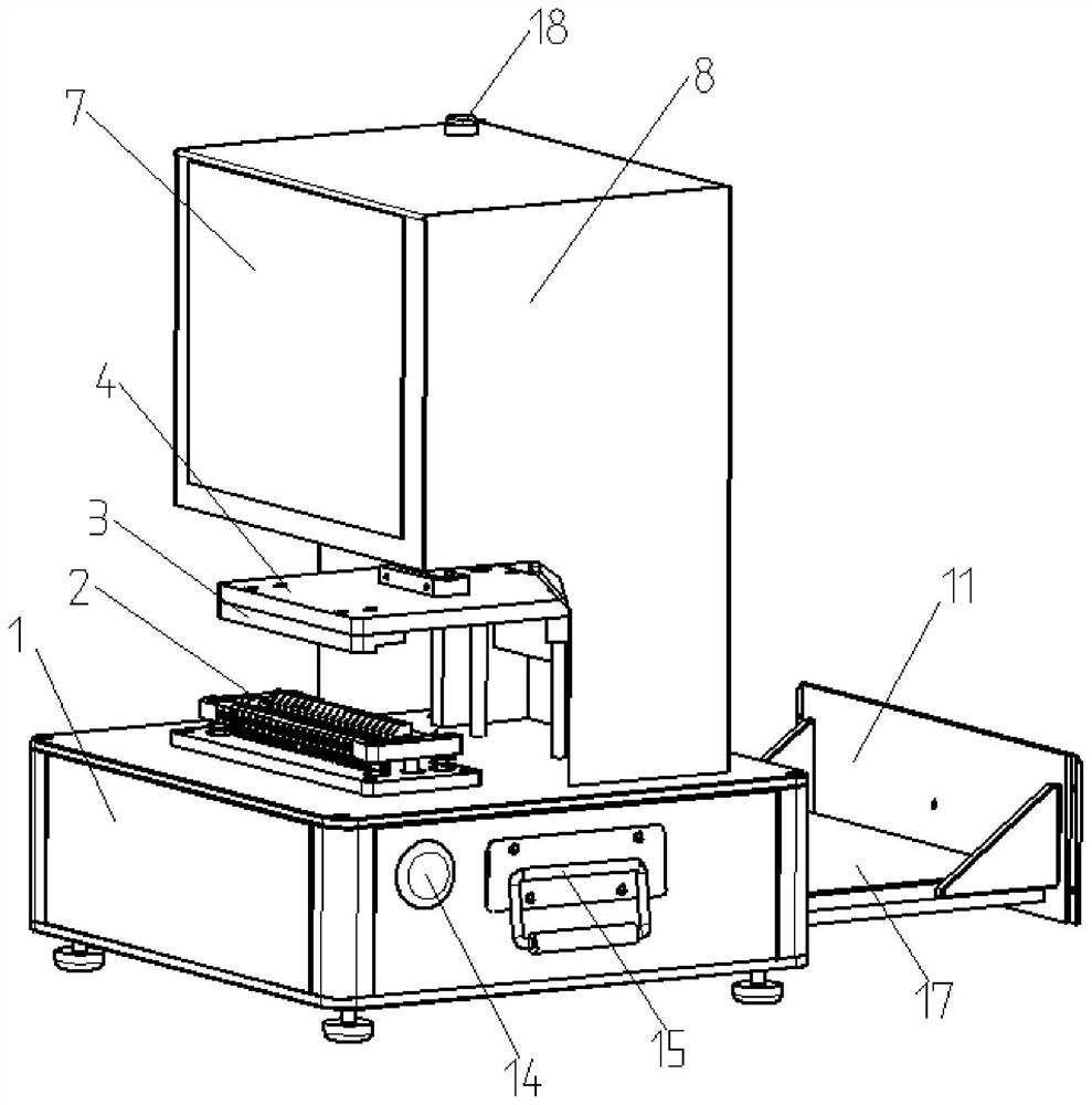
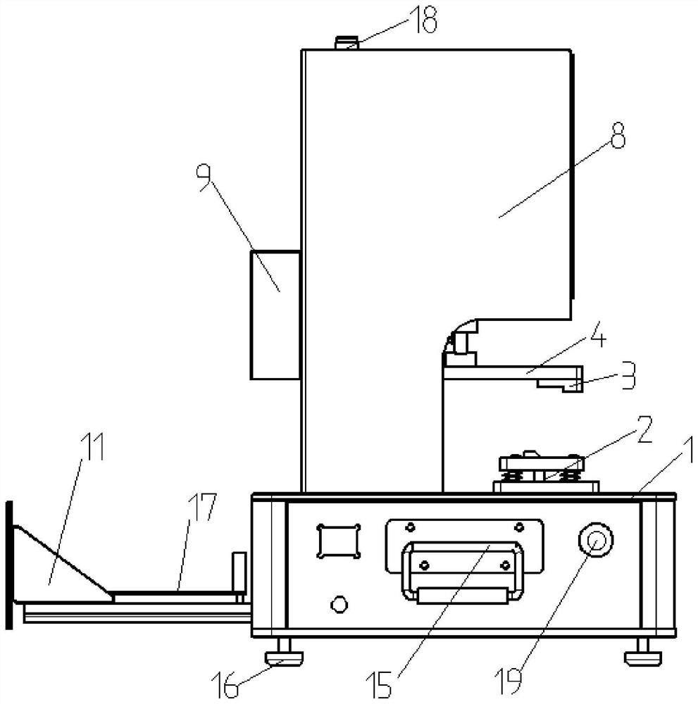
[0063] The embodiment of the present invention provides a detection device, please refer to Figure 1-14 , including: a detection table 1, a crimping mechanism that can move up and down, a detection connection part 2 and an installation structure 6. The detection connection part 2 and the installation frame 6 are arranged on the detection platform 1 at a distance, and the installation frame 6 fixes the crimping mechanism above the ...


PUM


Abstract

The invention relates to the technical field of civil explosive testing, and particularly discloses detection equipment. The detection equipment comprises a detection table, a crimping mechanism, a detection connecting part and a mounting framework. The detection connecting part and the mounting framework are arranged on the detection table in a spaced mode, and the mounting framework fixes the crimping mechanism above the detection connecting part. The detection connecting part comprises a probe plate provided with a plurality of probes, a telescopic supporting assembly, a module mounting plate and an explosion-proof structure used for separating explosive head parts of adjacent electronic detonator control modules. The probe plate is fixed on the detection table. The telescopic supporting assembly is arranged on the probe plate, and the module mounting plate is suspended above the probe plate. The explosion-proof structure is arranged on the module mounting plate. When the detection equipment is used for carrying out batch testing on the electronic detonator control modules, the situation of sympathetic detonation between the explosive heads of the adjacent electronic detonator control modules can be prevented, the production cost is reduced, and the equipment is high in overall framework integration degree, light, simple, easy to carry and beneficial to marketization transaction.

Description

technical field [0001] The invention relates to the technical field of civil explosion testing, in particular to a detection device and a detection method. Background technique [0002] The inherent advantages of electronic detonators such as safety, reliability, precision, and environmental protection have been widely recognized and used in the blasting industry. With the increase in the output of electronic detonators, the existing production and testing methods for control modules of electronic detonators It is more and more unsuitable to meet the current needs. The existing electronic detonator control module test equipment has complex structure and low integration. It is difficult to quickly achieve the desired effect by crimping the detection end of the electronic detonator control module during testing. The electronic detonator control module It is easy to contact abnormalities (such as open circuit, short circuit, etc.) between the detection terminal and the equipmen...

Claims


Application Information

Patent Timeline
Patent Type & Authority Applications(China)
IPC IPC(8): F42C21/00F42C19/12
CPCF42C21/00F42C19/12
Inventor 曾习文罗现洪谭津杨安科韩延江何荣宪
Owner BEIJING QAML OF SCI & TECH CO LTD
Why Eureka
Try Eureka