


Quick Research
Generate reliable direction feasibility study reports for your R&D in just a few steps.

Technical Q&A
Discover and master advanced knowledge NOW. Basics, ideas, possibilities, all at once.

Find Solutions
As an expert in R&D theories, this can generate solutions to your technical problems instantly.

Evaluate Feasibility
Analyze your overall solution with one click, know your potential R&D risks in advance.

Monitor Landscape
Get weekly tech updates, stay abreast of the latest tech innovations and key insights.
Manufacturing method of disc device suspension and suspension assembly used in said manufacturing method
A manufacturing method and a technology of a magnetic disk device, applied in the direction of the integrated arm assembly, the structure of the arm parts, the configuration/installation of the recording head, etc., which can solve the problems of poor positional accuracy and inability to fit smoothly
- Summary
- Abstract
- Description
- Claims
- Application Information
AI Technical Summary
Problems solved by technology
Method used
Image

Examples
no. 1 Embodiment
[0028] In this embodiment, the suspension for a magnetic disk device is manufactured by a load beam frame having a load beam and a flexure frame having a flexure. The structures applicable to the load beam frame, the flexure frame, and the suspension assembly overlapping the load beam frame and the flexure frame are illustrated below.
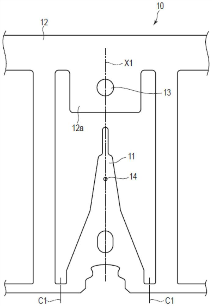
[0029] figure 1 It is a schematic plan view of the load beam frame 10 related to the first embodiment. The load beam frame 10 includes a load beam 11 and a first frame 12 . The load beam frame 10 is formed of a metal plate (leaf spring) by etching or pressing. The metal plate is formed of a metal material such as stainless steel, for example.
[0030] The load beam 11 extends along the axis X1. A dimple 14 is formed on the axis X1 of the load beam 11 . The first frame 12 is integrally connected with the load beam 11 . The first frame 12 is separated from the load beam 11 during the suspension manufacturing process. figure 1 The dotted li...
no. 2 Embodiment
[0062] The second embodiment will be described below. Components that are the same as those in the first embodiment are denoted by the same symbols, and explanations thereof are appropriately omitted. Figure 6 It is a schematic side view of the suspension unit 60 according to the second embodiment. Figure 7 is along Figure 6A brief partial cross-sectional view of the suspension assembly 60 at line C-C in FIG. In this embodiment, the convex portion 13 has an opening 13b. This point is different from the first embodiment. The opening 13 b may be formed at the center of the convex portion 13 or at a position deviated from the center of the convex portion 13 .
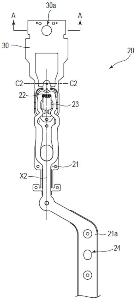
[0063] The load beam frame 10 is disposed on the base 70 . The base 70 has a pin P thereon, and the pin P is inserted into the opening 13b. exist Figure 7 , a gap is formed between the opening 13b and the pin P. By overlapping the load beam frame 10 along the pin P with the flexure frame 20 , the suspension ass...
PUM
| Property | Measurement | Unit |
|---|---|---|
| water contact angle | aaaaa | aaaaa |
Abstract
Description
Claims
Application Information
 - R&D Engineer
- R&D Manager
- IP Professional
- Industry Leading Data Capabilities
- Powerful AI technology
- Patent DNA Extraction
Browse by: Latest US Patents, China's latest patents, Technical Efficacy Thesaurus, Application Domain, Technology Topic, Popular Technical Reports.
© 2024 PatSnap. All rights reserved.Legal|Privacy policy|Modern Slavery Act Transparency Statement|Sitemap|About US| Contact US: help@patsnap.com