Moving target for neutron generation

A technology for moving targets and neutrons, which can be used in targets for generating nuclear reactions, X-ray/γ-ray/particle irradiation therapy, cooling/ventilation/heating transformation, etc., which can solve the problem of low neutron utilization efficiency and large equipment size. , complex structure and other problems, to achieve the effect of improving heat dissipation limitations, high heat exchange stability, and reducing heat deposition

Pending Publication Date: 2021-08-27
CHINA SPALLATION NEUTRON SOURCE SCI CENT +1
View PDF3 Cites 1 Cited by
  • Summary
  • Abstract
  • Description
  • Claims
  • Application Information

AI Technical Summary

Problems solved by technology

[0006] The purpose of the present invention is to provide a moving target for neutron generation, aiming to solve the problem that beryllium itself is toxic, brittle, and poor in machinability in the prior art. The use of beryllium as a target for neutron generation has the limitations, while the neutron yield is relatively low relative to lithium, the accelerator energy and power required for treatment are high, and the problem of high device cost; it also solves the problem that the planar static target in the prior art needs to be homogenized to reduce the proton beam The highest heat flux density, heat concentration and difficulty in heat dissipation; and the need to solve the problem that the conical and wedge-shaped targets in the prior art reduce the heat flux density per unit area, but the requirements for the accelerator are very high, and the beam loss is also increased; In addition, it is also necessary to solve the problems that the rotating target in the prior art has a complex structure, large equipment size, unfavorable coupling with the moderator, low neutron utilization efficiency, difficult installation and operation, and low stability

Method used


Image

  • Moving target for neutron generation
  • Moving target for neutron generation
  • Moving target for neutron generation

Examples


Embodiment Construction

[0038] Embodiments of the present invention are described in detail below, examples of which are shown in the drawings, wherein the same or similar reference numerals designate the same or similar elements or elements having the same or similar functions throughout. The embodiments described below by referring to the figures are exemplary and are intended to explain the embodiments of the present invention and should not be construed as limitations of the present invention.

[0039] In the description of the embodiments of the present invention, it should be understood that the terms "length", "width", "upper", "lower", "front", "rear", "left", "right", "vertical ", "horizontal", "top", "bottom", "inner", "outer" and other indicated orientations or positional relationships are based on the orientations or positional relationships shown in the drawings, and are only for the convenience of describing the embodiments of the present invention and simplifying Describes, but does no...


PUM


Abstract

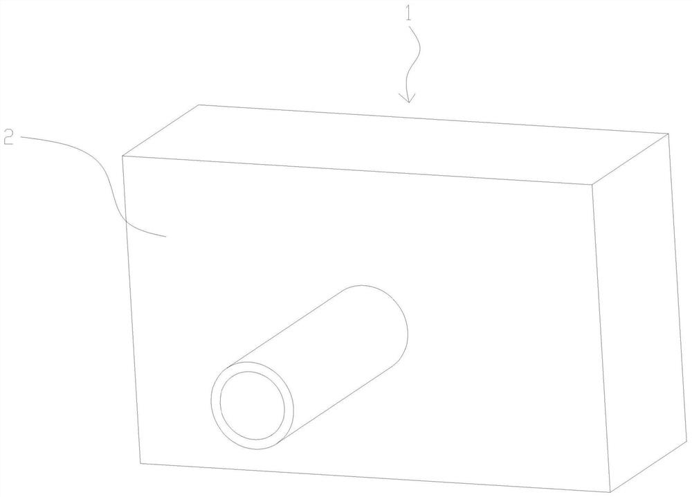
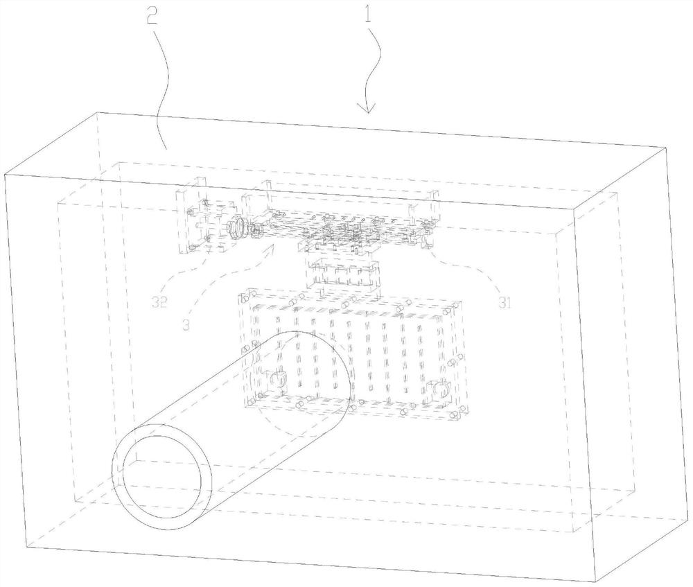
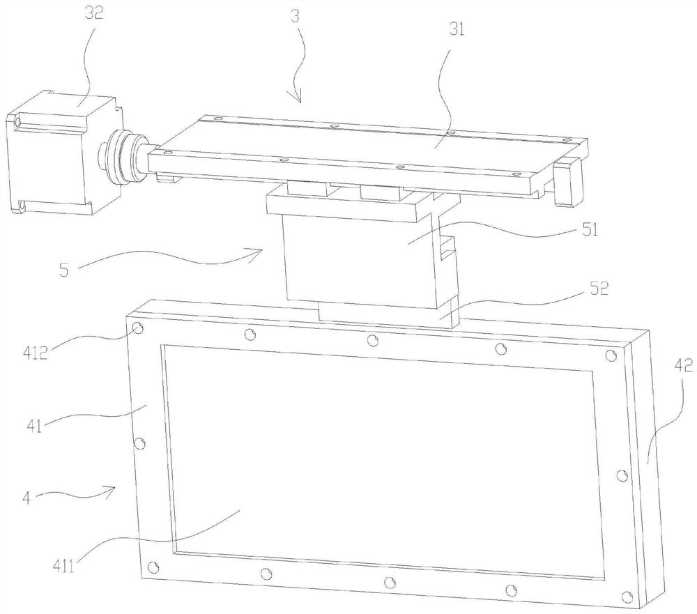
The invention provides a moving target for neutron generation. The moving target comprises a vacuum cavity, a moving device and a target body, wherein the moving device and the target body are installed in the vacuum cavity; the moving device is installed on the inner wall of the top of the vacuum cavity; the target body is detachably installed on the moving device through a hook assembly, and the moving device can control the reciprocating motion of the target body. The moving device is adopted to control the target body to move left and right in a reciprocating mode, so that the problem of high local heat caused by flow beam concentration of an existing static target is solved, heat deposition of the target body in unit volume is effectively reduced, the heat concentration peak value of the target body is also reduced, and the requirement for proton beam beams is reduced.

Description

technical field [0001] The invention relates to the technical field of neutron therapy, in particular to a neutron generating moving target used in a BNCT device. Background technique [0002] In cancer treatment and the like, radiation therapy is highly evaluated, and in particular, neutron capture therapy (BNCT: Neutron Capture Therapy) has attracted attention due to its possibility of selective therapy at the cell level in principle. In BNCT, stable isotopes with high capture cross-sections with neutrons enter cancer cells in advance, and neutrons undergo nuclear reactions with them to produce heavy ions with a short range and high LET (Linear Energy Transfer), killing cancer cells Cells have little effect on normal cells. At present, as BNCT, B, Gd and thermal neutrons or epithermal neutrons are used for cancer treatment. [0003] In recent years, neutron generators that accelerate protons to a specified energy by accelerators and irradiate specific targets to generate ...

Claims


Application Information

Patent Timeline
Patent Type & Authority Applications(China)
IPC IPC(8): H05H6/00H05H3/06H05K7/20A61N5/10
CPCH05H6/00H05H3/06H05K7/20272A61N5/1001A61N2005/1019A61N2005/109A61N2005/1092A61N2005/1087
Inventor 童剑飞孙鹏梁天骄傅世年
Owner CHINA SPALLATION NEUTRON SOURCE SCI CENT
Why Eureka
Try Eureka