Dust-air separation device applied to dust cup of dust collector and dust collector

A technology for dust and gas separation and vacuum cleaners, which is applied in the direction of vacuum cleaners, applications, suction filters, etc., and can solve the problem of low efficiency of dust and gas separation in dust cups of vacuum cleaners

Pending Publication Date: 2021-08-31
SUZHOU CHUNJU ELECTRIC CO LTD
View PDF0 Cites 1 Cited by
  • Summary
  • Abstract
  • Description
  • Claims
  • Application Information

AI Technical Summary

Problems solved by technology

[0004] In view of this, the present invention provides a dust-air separation device and a vacuum cleaner applied to the dust cup of a vacuum cleaner. It innovatively installs a filter channel and a cyclone cone in the dust cup. The spirally rising filter channel can allow the dust to be thrown away by centrifugal force when it advances At the same time, the concave cone shape of the nylon mesh cone on the cyclone cone can effectively improve the dust and gas separation effect, thus effectively solving the problem of low dust and gas separation efficiency of the dust cup of the vacuum cleaner

Method used


Image

  • Dust-air separation device applied to dust cup of dust collector and dust collector
  • Dust-air separation device applied to dust cup of dust collector and dust collector
  • Dust-air separation device applied to dust cup of dust collector and dust collector

Examples


Embodiment 1

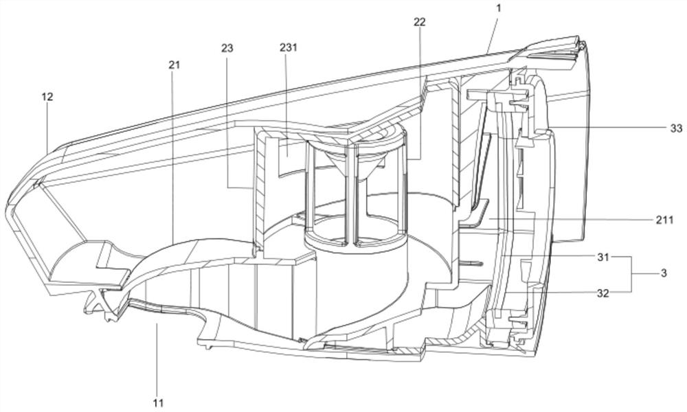
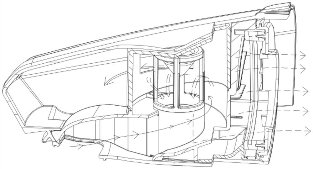
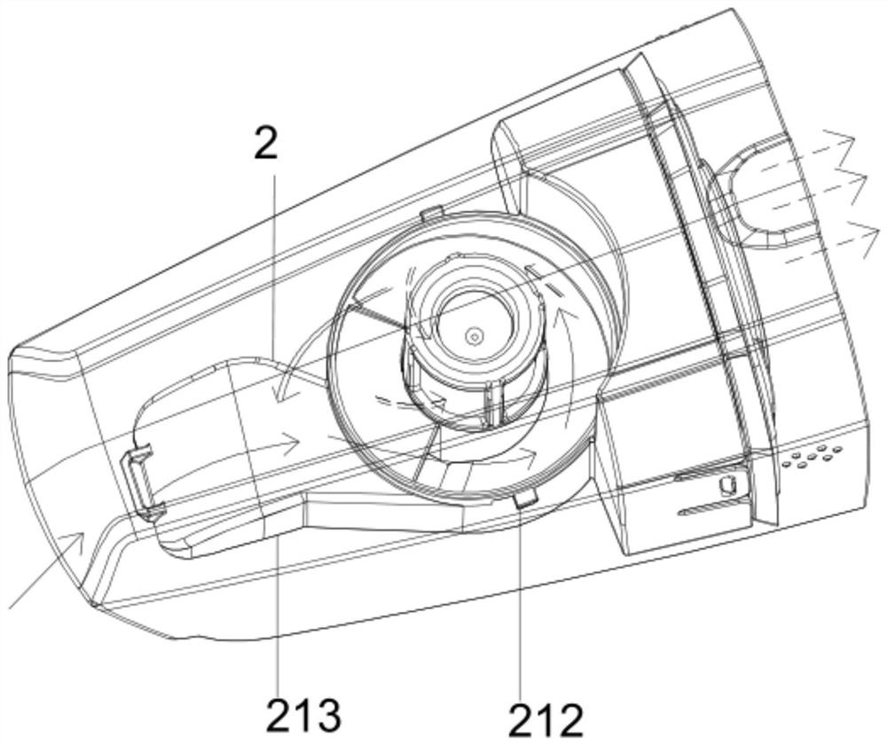
[0027] see Figure 1 to Figure 7 , the figure shows a dust and gas separation device applied to the dust cup of the vacuum cleaner provided by Embodiment 1 of the present invention, which includes a dust cup main body 1, an air inlet 11 is provided at the bottom of the dust cup main body 1, and the dust cup main body 1 A dust bucket 12 is arranged on the top, and a dust-gas separation component 2 is arranged in the dust-gas bucket 12. The dust-gas separation component 2 includes a filter channel 21 and a cyclone cone 22. One end of the filter channel 21 is connected with the air inlet 11, and the filter channel The other end of 21 is provided with an air outlet 211, and the filter channel 21 spirally rises, and the cyclone cone 22 is installed above the filter channel 21, and the filter channel 21 is connected with a dust-removing wind cover 23, and the cyclone cone 22 is located in the dust-removing wind cover 23 , the ash-throwing wind cover 23 is provided with an ash-throwi...

Embodiment 2

[0036] see Figure 1 to Figure 7 , the figure shows a dust and gas separation device applied to the dust cup of the vacuum cleaner provided by the second embodiment of the present invention. This embodiment further makes the following technical solutions as improvements on the basis of the above-mentioned embodiments: The cyclone cone 22 is provided with a nylon mesh cone 221, and the interior of the nylon mesh cone 221 has a concave cone surface. After testing and research, we found that the concave cone shape of the nylon mesh cone can effectively improve the separation effect. According to the test data, the vacuum degree will lose 8% more without the concave conical surface.

Embodiment 3

[0038] see Figure 1 to Figure 7, the figure shows a dust and gas separation device applied to the dust cup of the vacuum cleaner provided by the third embodiment of the present invention. This embodiment further makes the following technical solutions as improvements on the basis of the above-mentioned embodiments: Get rid of ash mouth 231 and offer on the circumferential side wall of get rid of ash wind cover 23, the dust direction that throws off from ash port 231 is tangent to the tangential extension line of the opening position of get rid of ash port 231. In the above improvement, the ash-throwing port is set on the circumferential side wall of the dust-throwing wind hood, and the direction of the dust thrown out from the ash-throwing port is tangent to the tangential extension line of the opening position of the ash-throwing port. , due to the effect of centrifugal force, the wind speed in the area of ​​the ash throwing port is fast, and the dust will be blown up again ...


PUM


Abstract

The invention provides a dust-air separation device applied to a dust cup of a dust collector, which comprises a dust cup main body, wherein an air inlet is arranged at the bottom of the dust cup main body, a dust accumulation barrel is arranged on the dust cup main body, a dust-air separation component is arranged in the dust accumulation barrel, the dust-air separation component comprises a filter channel and a cyclone cone, one end of the filter channel is communicated with the air inlet, an air outlet is formed in the other end of the filter channel, the filter channel spirally ascends, the cyclone cone is installed above the filter channel, an dust throwing fan cover is connected to the filter channel, the cyclone cone is located in the dust throwing fan cover, a dust throwing opening is formed in the dust throwing fan cover, dust-containing airflow enters the filter channel from the air inlet and is separated through the cyclone cone, then dust is thrown out of the dust throwing opening and enters the dust accumulation barrel, and the filtered dust-containing airflow flows out of the air outlet. The invention further provides the dust collector. Compared with the prior art, the problem that the dust cup of the dust collector is low in dust-air separation efficiency can be effectively solved.

Description

technical field [0001] The invention relates to the field of vacuum cleaners, in particular to a dust and gas separation device applied to a dust cup of a vacuum cleaner and a vacuum cleaner. Background technique [0002] A vacuum cleaner is a commonly used cleaning device that can generate very strong suction to suck dust or foreign matter accumulated on floors, carpets, walls, or other surfaces into its garbage collection device. When the vacuum cleaner is working, the motor of the vacuum cleaner generates negative pressure inside the dust bucket to generate suction, so that the air containing dust or foreign matter is sucked in through the suction nozzle and the connecting hose, and passes through the air filter device (such as a filter, etc.) , can separate larger particles of dust and foreign matter from the air, and collect them into the dust bucket, and then discharge the treated air through the exhaust grille set on the casing. [0003] At present, the separation ef...

Claims


Application Information

Patent Timeline
IPC IPC(8): A47L9/16
CPCA47L9/16A47L9/1608A47L9/1666
Inventor 王超干
Owner SUZHOU CHUNJU ELECTRIC CO LTD
Why Eureka
Try Eureka