Computer room dedusting equipment
A technology of computer room and dust removal equipment, applied in the direction of dust removal, external electrostatic separator, electrode structure, etc., can solve the problem of incomplete dust removal
- Summary
- Abstract
- Description
- Claims
- Application Information
AI Technical Summary
Problems solved by technology
Method used
Image

Examples
specific Embodiment approach 1
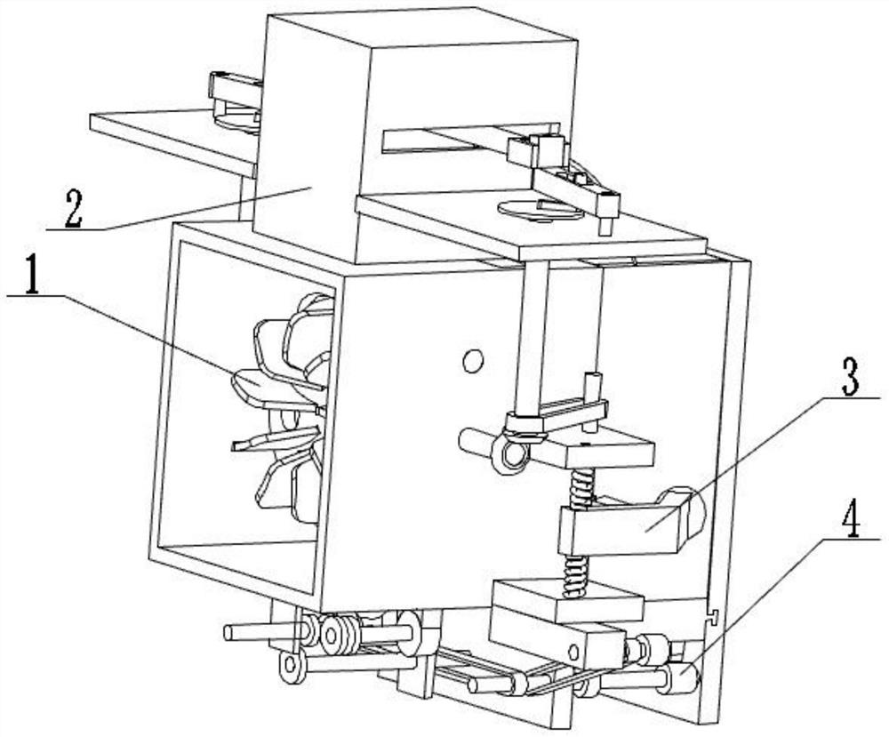
[0030] Combine below figure 1 , figure 2 , image 3 , Figure 4 , Figure 5 , Figure 6 , Figure 7 , Figure 8 , Figure 9 , Figure 10 , Figure 11 , Figure 12, Figure 13 , Figure 14 , Figure 15 Describe this embodiment, the present invention relates to a computer room equipment, more specifically a computer room dust removal equipment, including a dust suction mechanism, a dust removal mechanism, a dust removal mechanism, a dust transport mechanism, and the equipment can clean the dust in the computer room. Suction, the equipment can filter the dust in the air, the equipment can remove the dust on the electrode plate, the equipment can collect the dust and dump it out of the equipment.
[0031] The dust suction mechanism is connected with the dust removal mechanism, the dust removal mechanism is connected with the dust removal mechanism, and the dust transportation mechanism is connected with the dust suction mechanism.
specific Embodiment approach 2
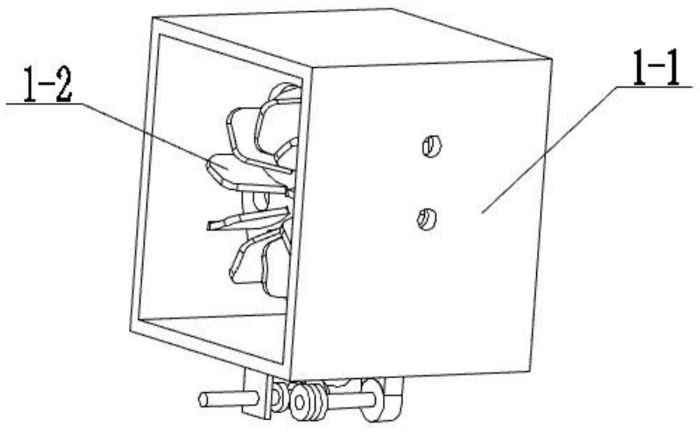
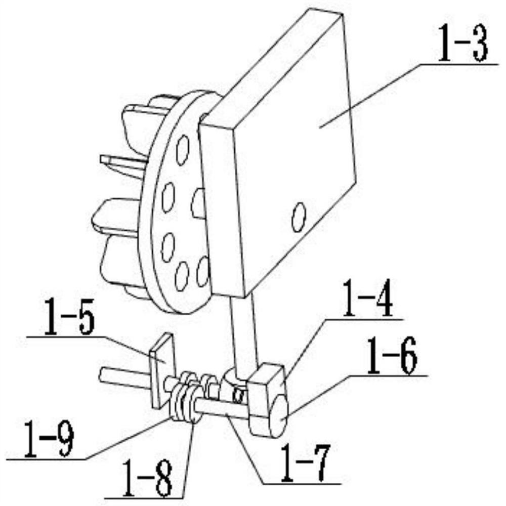
[0033] Combine below figure 1 , figure 2 , image 3 , Figure 4 , Figure 5 , Figure 6 , Figure 7 , Figure 8 , Figure 9 , Figure 10 , Figure 11 , Figure 12 , Figure 13 , Figure 14 , Figure 15 Describe this embodiment, this embodiment will further explain the first embodiment, the dust suction mechanism 1 includes a gas pipeline 1-1, a blade 1-2, a mounting plate a1-3, a motor mounting seat 1-4, and a mounting plate b1 -5, motor 1-6, motor shaft 1-7, gear a1-8, gear b1-9, gear c1-10, gear d1-11, rotating column a1-12, helical gear a1-13, helical gear b1- 14. Rotating column b1-15, helical gear c1-16, rotating column c1-17, helical gear d1-18, wheel with holes 1-19, gas pipeline 1-1 is connected with mounting plate a1-3, gas pipeline 1 -1 is connected to the motor mounting base 1-4, the gas pipeline 1-1 is connected to the mounting plate b1-5, the gas pipeline 1-1 is connected to the rotating column b1-15 bearing, and the blade 1-2 is connected to the pe...
specific Embodiment approach 3
[0035] Combine below figure 1 , figure 2 , image 3 , Figure 4 , Figure 5 , Figure 6 , Figure 7 , Figure 8 , Figure 9 , Figure 10 , Figure 11 , Figure 12 , Figure 13 , Figure 14 , Figure 15 Describe this embodiment, this embodiment will further explain the first embodiment, the dust removal mechanism 2 includes an insulating box 2-1, a mounting plate c2-2, a helical gear e2-3, a rotating column d2-4, and a rotating column e2 -5, belt a2-6, rotating column f2-7, helical gear f2-8, helical gear g2-9, rotating column g2-10, electrode plate 2-11, magnet 2-12, conductor bar 2-13, wire 2-14, roulette 2-15, cylindrical pin 2-16, connecting rod 2-17, long pin 2-18, connecting rod with holes 2-19, rotating pin 2-20, square 2-21, insulating arched plate 2-22, oblong pin 2-23, the insulating box body 2-1 is connected with the gas pipeline 1-1, the insulating box body 2-1 is connected with the mounting plate c2-2, and the insulating box body 2-1 is connected wit...
PUM
 Abstract
Description
Claims
Application Information
 - R&D Engineer
- R&D Manager
- IP Professional
- Industry Leading Data Capabilities
- Powerful AI technology
- Patent DNA Extraction
Browse by: Latest US Patents, China's latest patents, Technical Efficacy Thesaurus, Application Domain, Technology Topic.
© 2024 PatSnap. All rights reserved.Legal|Privacy policy|Modern Slavery Act Transparency Statement|Sitemap