
Grinding device for side wall and end face of bearing ring

A technology of bearing rings and end faces, which is applied in the direction of grinding drive devices, grinding machines, grinding frames, etc., can solve the problems of low grinding efficiency and precision, large space occupation, and difficulty in coordination, and achieve low cost and small space occupation , the effect of shortening the processing cycle

Pending Publication Date: 2021-08-31
安徽省肥东宏达轴承配件有限公司
View PDF14 Cites 5 Cited by
  • Summary
  • Abstract
  • Description
  • Claims
  • Application Information

AI Technical Summary

Problems solved by technology

[0004] For some small and medium-sized bearing inner rings, due to their generally small size, if manual grinding is used, that is, the operator holds the grinding wheel to carry out the grinding operation, not only the workload is large, but also the grinding efficiency and accuracy are low; If mechanical equipment such as machine tools is used to carry out grinding operations, it is necessary to design and manufacture corresponding complex-structured clamping tools, grinding tools, and supporting feeding, retrieving, rotating, driving and other tooling, which will bring high cost and occupy space. Large size, cumbersome operation, difficult coordination and many other problems

Method used


Image

  • Grinding device for side wall and end face of bearing ring
  • Grinding device for side wall and end face of bearing ring
  • Grinding device for side wall and end face of bearing ring

Examples


Embodiment Construction

[0037] The following will clearly and completely describe the technical solutions in the embodiments of the present invention with reference to the accompanying drawings in the embodiments of the present invention. Obviously, the described embodiments are only some, not all, embodiments of the present invention. Based on the embodiments of the present invention, all other embodiments obtained by persons of ordinary skill in the art without making creative efforts belong to the protection scope of the present invention.

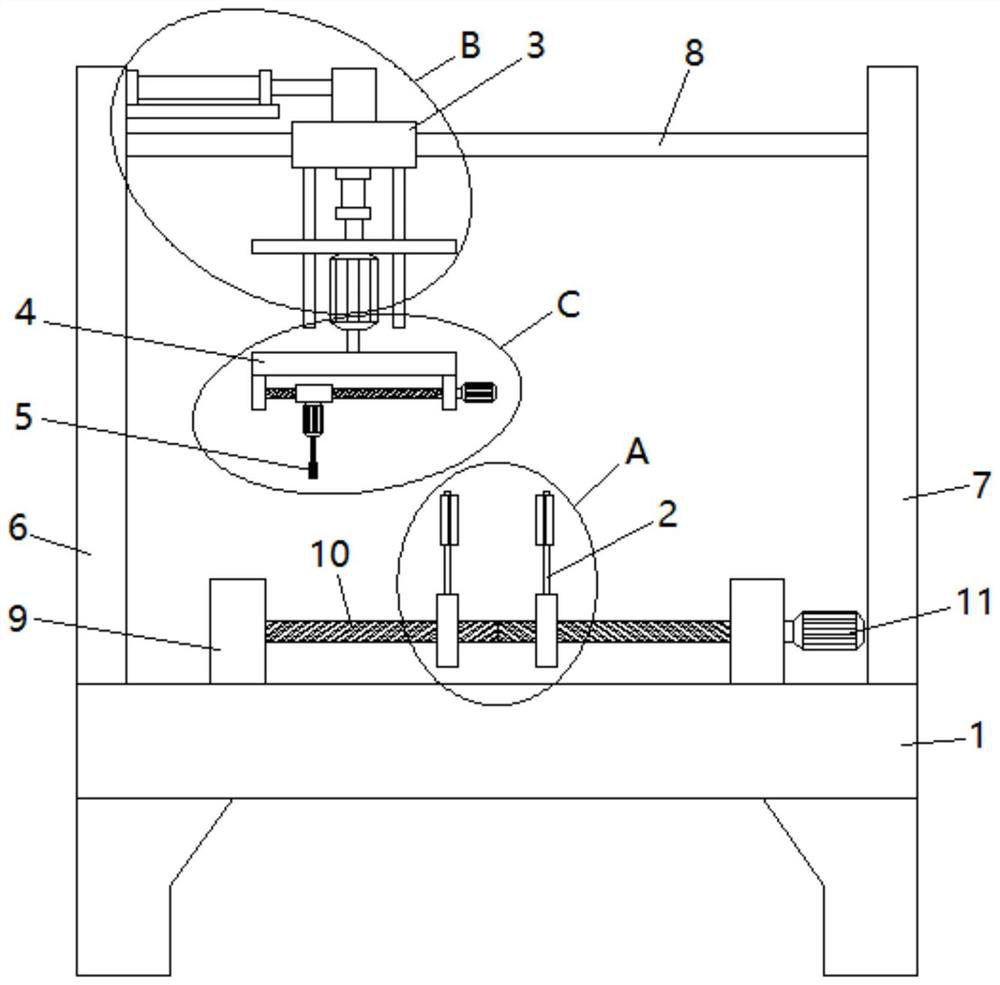
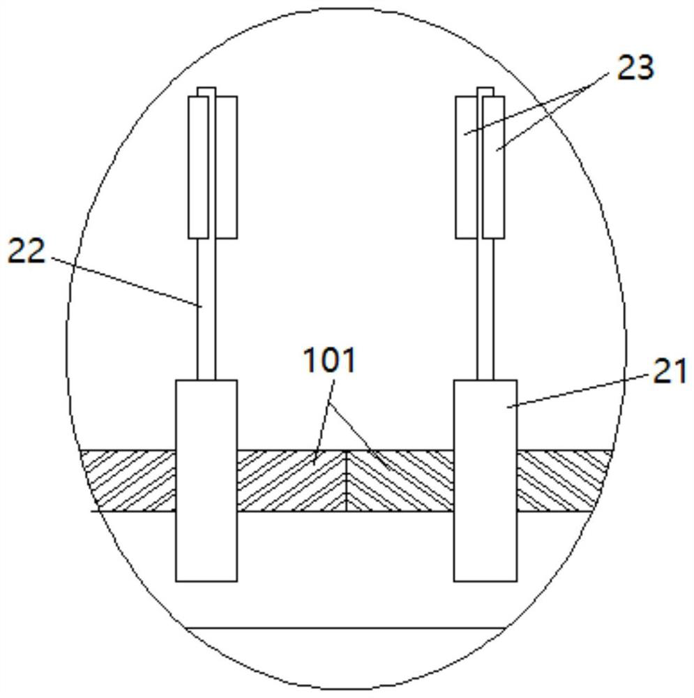
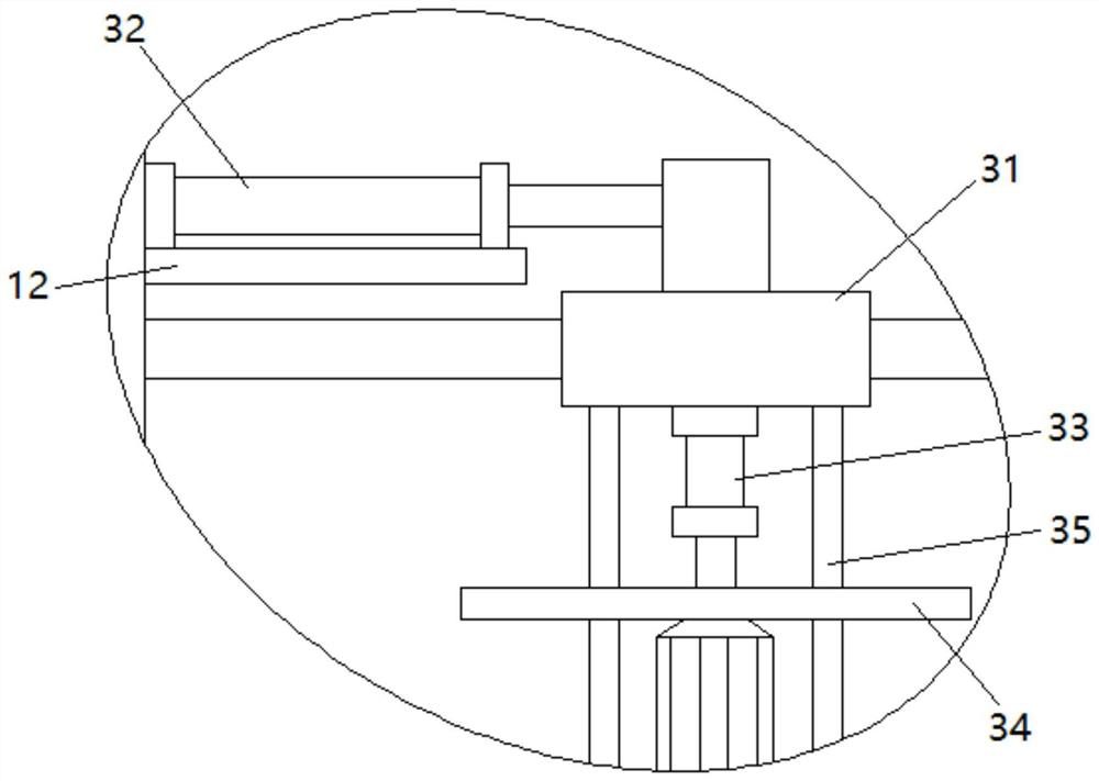
[0038] see Figure 1-5 , a side wall and end surface grinding device of a bearing ring, including a workbench 1, two clamping mechanisms 2, a traverse lifting mechanism 3, a rotating mechanism 4 and a grinding mechanism 5, and the two ends of the workbench 1 correspond to A left column 6 and a right column 7 are fixedly connected, and a beam 8 is fixedly connected between the tops of the left column 6 and the right column 7. Two clamping mechanisms 2 are insta...


PUM


Abstract

The invention discloses a grinding device for the side wall and the end face of a bearing ring. The grinding device comprises a workbench, two clamping mechanisms, a transverse moving and lifting mechanism, a rotating mechanism and a grinding mechanism, wherein the two clamping mechanisms can correspondingly clamp the bearing ring from the two sides of the outer portion or correspondingly expand the bearing ring from the two sides of the inner portion, and the distance between the two clamping pieces is adjustable; the transverse moving and lifting mechanism can drive the rotating mechanism and the grinding mechanism to transversely move and lift; the grinding mechanism is arranged at the eccentric position of the rotating mechanism and driven by the rotating mechanism to rotate, and the distance between the grinding mechanism and the center position of the rotating mechanism is adjustable; and the grinding mechanism can grind the inner wall, the outer wall, the upper end face and the lower end face of the bearing ring in the circumferential direction. The grinding device is simple in structure, small in occupied space, low in cost, easy and convenient to operate, high in working efficiency, capable of meeting the requirement for grinding the bearing rings with different diameters and suitable for grinding the small and medium-sized bearing rings.

Description

technical field [0001] The invention relates to the technical field of bearing production and processing equipment, in particular to a side wall and end face grinding device of a bearing ring. Background technique [0002] A bearing ring is an annular part of a radial rolling bearing with one or several raceways, generally also called a bearing inner ring or a bearing outer ring, and is one of the important parts of a bearing. [0003] Grinding the side wall (including the inner and outer walls) and the end face (including the upper and lower end faces) of the bearing ring is an indispensable process in the production and processing of the bearing ring. The physical properties of the side wall and end face, in order to obtain a specific surface roughness, so as to improve the mechanical properties of the bearing inner ring. [0004] For some small and medium-sized bearing inner rings, due to their generally small size, if manual grinding is used, that is, the operator holds...

Claims


Application Information

Patent Timeline
IPC IPC(8): B24B5/01B24B41/02B24B41/06B24B47/04B24B47/22B24B47/12
CPCB24B5/01B24B41/02B24B41/06B24B47/04B24B47/22B24B47/12
Inventor 张国权
Owner 安徽省肥东宏达轴承配件有限公司
Learn More