3D printing device for parts for home design

A 3D printing and home design technology, applied in manufacturing auxiliary devices, 3D object support structures, metal processing equipment, etc., can solve problems such as endangering health and delaying production efficiency, and achieve the effect of improving work efficiency

Active Publication Date: 2021-08-31
深圳万知达科技有限公司
View PDF3 Cites 1 Cited by
  • Summary
  • Abstract
  • Description
  • Claims
  • Application Information

AI Technical Summary

Problems solved by technology

[0003] Some parts of home design are usually printed by 3D printing equipment, but when 3D printing equipment is printed, after each layer of powder is sintered by the laser, it is necessary to use scraper gas to recover the excess powder; after the printing is completed, the excess powder also needs to be cleaned Recycling; when powder is recycled, the equipment is usually closed, the door of the 3D printing equipment is opened to take out the powder inside the equipment, and the powder remaining in the front pipe and the rear wall pipe of the equipment are collected; equipment shutdown greatly delays production efficiency; and 3D printing When the printing equipment is printing, the powder is blown out of the equipment, mixed with air and inhaled by the operator, which will endanger people's health

Method used


Image

  • 3D printing device for parts for home design
  • 3D printing device for parts for home design
  • 3D printing device for parts for home design

Examples


Embodiment Construction

[0025] The following will clearly and completely describe the technical solutions in the embodiments of the present invention with reference to the accompanying drawings in the embodiments of the present invention. Obviously, the described embodiments are only some, not all, embodiments of the present invention.

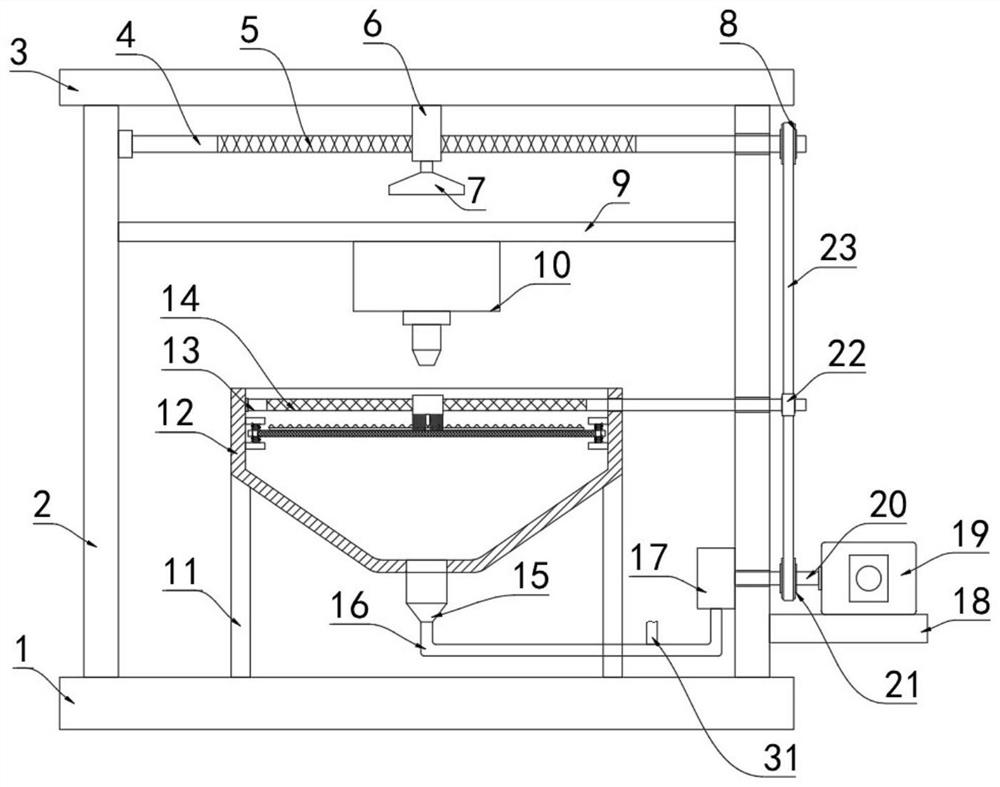
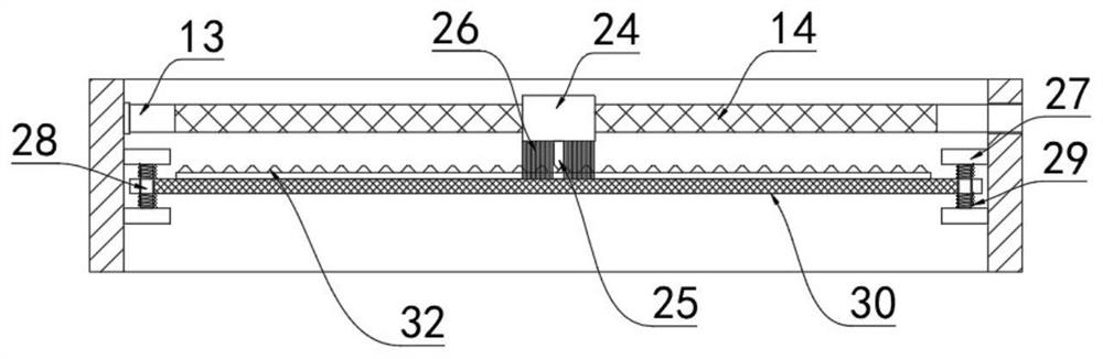
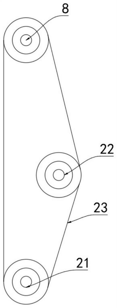
[0026] refer to Figure 1-4 , a 3D printing device for home design components, comprising a base 1, a support frame 2 is fixedly connected to the base 1, a horizontal plate 3 is fixedly connected to the upper end of the support frame 2, a support plate 9 is fixedly connected to the inner wall of the support frame 2, and the support A 3D printer 10 is fixedly installed on the bottom of the plate 9, and the 3D printer 10 is a prior art, so it will not be repeated here; a first rotating rod 4 is arranged between the support plate 9 and the horizontal plate 3, and the first rotating rod 4 is connected to the horizontal plate 3. One side of the inner wall of the support f...


PUM


Abstract

The invention discloses a 3D printing device for parts for home design. The 3D printing device comprises a base, wherein a supporting frame is fixedly connected to the base, a transverse plate is fixedly connected to the upper end of the supporting frame, a supporting plate is fixedly connected to the inner wall of the supporting frame, and a D printer is fixedly installed at the bottom of the supporting plate; a first rotating rod is arranged between the supporting plate and the transverse plate, the first rotating rod is rotationally connected with the inner wall of one side of the supporting frame, the other end of the first rotating rod penetrates through the supporting frame and is rotationally connected with the supporting frame, and the middle of the first rotating rod is a first reciprocating lead screw; and a first sliding block abutting against the transverse plate and slidably connected with the transverse plate is arranged at the bottom of the transverse plate, and the first reciprocating lead screw penetrates through the first sliding block and is connected with the first sliding block in a matched manner. According to the 3D printing device, powder can be effectively removed through one driving motor, and meanwhile, a screen plate can be vibrated and cleaned, cleaning and collecting of the powder can be achieved without stopping the 3D printing equipment, and the working efficiency is improved.

Description

technical field [0001] The invention relates to the technical field of home design, in particular to a 3D printing device for home design components. Background technique [0002] 3D printer, also known as three-dimensional printer (3DP), is a cumulative manufacturing technology, that is, a machine of rapid prototyping technology. It is based on a digital model file and uses special wax, powdered metal or plastic to bond materials, which create three-dimensional objects by printing layers of adhesive materials. At this stage 3D printers are used to manufacture products. The technology of constructing objects by printing layer by layer. The principle of a 3D printer is to put data and raw materials into the 3D printer, and the machine will build the product layer by layer according to the program. [0003] Some parts of home design are usually printed by 3D printing equipment, but when 3D printing equipment is printed, after each layer of powder is sintered by the laser, i...

Claims


Application Information

Patent Timeline
Patent Type & Authority Applications(China)
IPC IPC(8): B29C64/357B29C64/35B33Y40/00
CPCB29C64/357B29C64/35B33Y40/00
Inventor 汪明镜郭乘伸杲颖李鹏程郜世萌于睿
Owner 深圳万知达科技有限公司
Why Eureka
Try Eureka