A creeping vehicle speed control system and its control method

A vehicle speed control and creeping technology, which is applied in the field of vehicle control, can solve the problems of not being able to meet the driver's different needs for creeping speed, and not considering the different needs of different drivers, so as to reduce the frequency of operating the accelerator and braking , Realize real-time adjustment and reduce driving intensity

Active Publication Date: 2021-10-12
南通睿动新能源科技有限公司
View PDF0 Cites 0 Cited by
  • Summary
  • Abstract
  • Description
  • Claims
  • Application Information

AI Technical Summary

Problems solved by technology

[0003] At the same time, the current creeping speed control methods all consider external factors such as vehicles or roads, in order to obtain a relatively fixed target creeping speed, without considering the differentiated needs of different drivers.
In reality, drivers with different levels of proficiency have different requirements for creeping speed, and the same driver has different requirements for creeping speed in the forward direction and backward direction of the vehicle. Therefore, the existing creeping speed control method Unable to meet the driver's differentiated needs for creeping speed

Method used


Image

  • A creeping vehicle speed control system and its control method
  • A creeping vehicle speed control system and its control method
  • A creeping vehicle speed control system and its control method

Examples


Embodiment 1

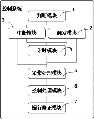
[0054] figure 1 A schematic structural diagram of a creeping vehicle speed control system provided by an embodiment of the present invention; this embodiment provides a creeping vehicle speed control system, including:

[0055] Judgment module 1, used to detect whether the current vehicle state meets the correction condition of creeping vehicle speed;

[0056] A trigger module 2, configured to generate a trigger command when the current vehicle state meets the correction condition of the creeping vehicle speed;

[0057] Interrupt module 3, when detecting that the current vehicle state does not meet the correction condition of creeping vehicle speed, generate an interrupt command;

[0058] The timing module 4 is used to record the time period data between each generated trigger instruction and the corresponding generated interrupt instruction;

[0059] Acquisition and processing module 5, used for collecting and processing creeping parameter information in time period data ac...

Embodiment 2

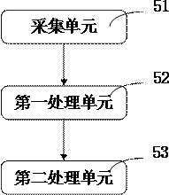
[0064] As an implementable way, on the basis of the above-mentioned embodiments, refer to the attached Figure 2-3 It can be seen that, in order to further improve the reliability of the creeping vehicle speed control system, the acquisition processing module 5 includes: an acquisition unit 51 for n The real-time vehicle speed and road slope are collected according to a fixed time interval, and the fixed time interval can be calibrated, such as 0.1S, etc.;

[0065] The first processing unit 52 is used for according to the time period data t n The arithmetic mean value of each vehicle speed and road gradient collected in the network is taken as the average vehicle speed V n and the average road slope i n ; The second processing unit 53 is used to generate the average vehicle speed V n Compare with the pre-stored creep target vehicle speed V to obtain the difference δV n .

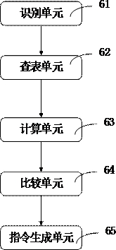
[0066] Control processing module 6 includes:

[0067] The identification unit 61 is used to judge w...

Embodiment 3

[0075] Figure 4 It is a schematic flow chart of a creeping vehicle speed control method provided by an embodiment of the present invention; this embodiment provides a creeping vehicle speed control method, and the execution subject of the creeping vehicle speed control method may be a creeping vehicle speed control system, Specifically, the following steps are included:

[0076] S100. Detecting whether the current vehicle state meets the correction condition for creeping vehicle speed;

[0077] S200. When the current vehicle state satisfies the correction condition of the creeping vehicle speed, generate a trigger instruction;

[0078] S300. When it is detected that the current vehicle state does not meet the correction condition of the creeping vehicle speed, an interrupt command is generated;

[0079] S400. Record the time period data between each generated trigger instruction and the corresponding generated interrupt instruction;

[0080] S500. Collect and process creep...


PUM


Abstract

The invention discloses a creeping vehicle speed control system, which comprises: a judging module detecting whether the current vehicle state meets the correction condition of the creeping vehicle speed; a triggering module generating a trigger command when the current vehicle state satisfies the correction condition of the creeping vehicle speed; When the interrupt module detects that the current vehicle state does not meet the correction conditions of the creeping vehicle speed, it generates an interrupt command; the acquisition processing module collects and processes the creep parameter information within the time period data according to the trigger command and the interrupt command; the control processing module identifies the acquisition module When the number of creep information collected reaches a preset value, the acquired creep parameter information is processed to generate a correction control instruction; the creep correction module corrects the target creep vehicle speed according to the correction control instruction and according to a preset correction rule. The invention can reduce the frequency of accelerator and brake operation by the driver during creeping, reduce the driving intensity, better realize the real-time adjustment of the target creeping speed, and meet the differential requirements of the driver on the creeping speed.

Description

technical field [0001] The invention relates to the technical field of automobile control, in particular to a creeping vehicle speed control system and a control method thereof. Background technique [0002] At present, there are many ways to control the creep speed, some of which are controlled by base creep torque or base creep torque plus compensation torque. This control method will give the same creep target torque under the same road conditions, thus Drive the vehicle to achieve the same target creep speed; there is a closed-loop speed or speed control to achieve creep speed control. This control method controls the output torque through the difference between the current speed (or speed) and the target speed (or speed), which can Achieve the same target creep speed under different road conditions. [0003] At the same time, the current creeping speed control methods all consider external factors such as vehicles or roads, in order to obtain a relatively fixed target ...

Claims


Application Information

Patent Timeline
Patent Type & Authority Patents(China)
IPC IPC(8): B60W30/18B60W40/105
CPCB60W30/18063B60W40/105
Inventor 熊峰
Owner 南通睿动新能源科技有限公司
Why Eureka
Try Eureka