Automatic continuous sewing device of mock button hole machine

A technology of artificial eye machine and mobile device, which is applied in the direction of cloth feeding mechanism, cloth pressing mechanism, sewing equipment, etc., and can solve problems such as single function, low processing efficiency, and too long swing mechanism

Inactive Publication Date: 2021-08-31
WENZHOU GUTAI MACHINERY TECH CO LTD
View PDF1 Cites 0 Cited by
  • Summary
  • Abstract
  • Description
  • Claims
  • Application Information

AI Technical Summary

Problems solved by technology

[0003] But this utility model has the following problems: the swing mechanism is too long, resulting in a large volume of the whole mechanism, which is difficult to place and carry, while the existing automatic sewing device for small artificial eye machines can only sew simple tracks, and has a single function. When the artificial eye machine needs to sew inclined artificial eyes, it is necessary to adjust the initial position of the clamping mechanism and change the initial position and direction of the fabric. However, the employees will have habitual movements during the long-term processing process, which leads to processing after changing the shape of the artificial eye each time. low efficiency

Method used


Image

  • Automatic continuous sewing device of mock button hole machine
  • Automatic continuous sewing device of mock button hole machine
  • Automatic continuous sewing device of mock button hole machine

Examples


specific Embodiment approach

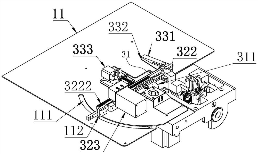
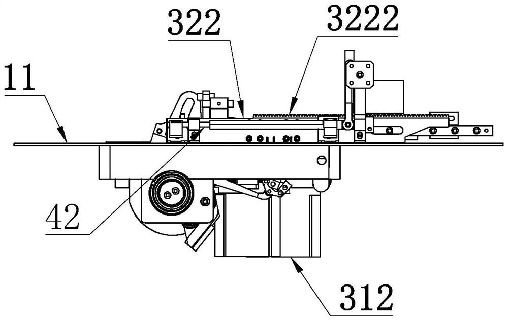
[0036] As an improved specific implementation, several pulleys 32211 are provided on the lower side of the sliding bar 3221 .

[0037] Through the above technical solution, the pulley 32211 is in conflict with the support groove 3211, which reduces friction, reduces power consumption of the reciprocating motor 323, saves energy and protects the environment, reduces wear and prolongs service life.

[0038] As an improved specific embodiment, the lower clamping plate 331 is provided with a lower protrusion 3311 , and the upper clamping plate 332 is provided with several upper protrusions 3321 , and the lower protrusions 3311 and the upper protrusions 3321 are dislocated.

[0039] Through the above technical solution, when the lower clamping plate 331 and the upper clamping plate 332 clamp the cloth, the upper protrusion 3321 and the lower protrusion 3311 are respectively located on the upper and lower sides of the cloth, and the upper protrusion 3321 and the lower protrusion 3311...

Embodiment approach

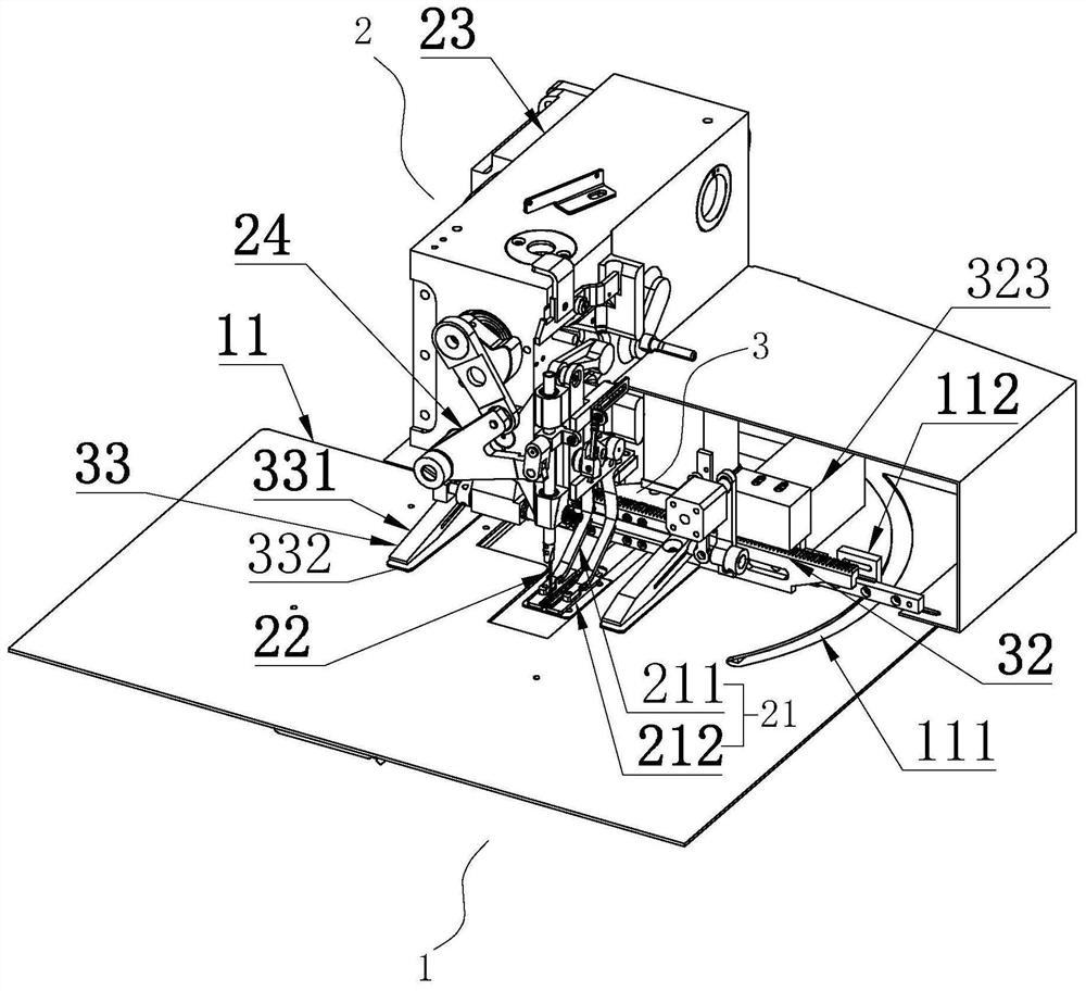
[0046] As an improved specific embodiment, the presser foot device 21 includes two pressing rods 211, the ends of the pressing rods 211 are provided with pressing plates 212, and the pressing plates 212 are located on both sides of the sewing needle 22 respectively. An accommodating area 213 is provided between the rods 211 , and the driving rod 43 , the push rod 44 and the clamping cylinder 333 are located in the accommodating area 213 .

[0047] Through the above-mentioned technical scheme, the two pressing rods 211 respectively drive the two pressing plates 212 to press the two sides of the sewing needle 22, so as to avoid skipped stitches during sewing and have high stability. At the same time, the driving rod 43, the push rod 44 and the clamping cylinder 333 are located In the accommodation area 213, it is located between the two clamping parts 334. When the program controls the clamping part 334 to clamp the cloth, the operation of the clamping cylinder 333 drives the pus...


PUM


Abstract

The invention discloses an automatic continuous sewing device of a mock button hole machine. According to the technical scheme, a cloth moving device is arranged on an operation table; the cloth moving device comprises a cloth rotating mechanism, a cloth reciprocating mechanism and a cloth clamping mechanism; the cloth rotating mechanism comprises a rotating table and a rotating motor; the rotating motor drives the rotating table to rotate; the cloth reciprocating mechanism comprises a supporting rod, a reciprocating rod and a reciprocating motor; the supporting rod is fixedly arranged on the rotating table; the reciprocating rod is connected to the supporting rod in a sliding mode; the reciprocating motor is fixed to the supporting rod and used for driving the reciprocating rod to move; the cloth clamping mechanism is arranged on the reciprocating rod and comprises a lower clamping plate, an upper clamping plate and a clamping air cylinder; and the clamping air cylinder is connected with the upper clamping plate, and controls whether the upper clamping plate is clamped with the lower clamping plate or not. The automatic continuous sewing machine is small in size, high in stability, diversified in sewing track and high in processing efficiency.

Description

technical field [0001] The invention relates to the field of sewing machine equipment, in particular to an automatic continuous sewing device for a false eye machine. Background technique [0002] The utility model patent whose authorization notification number is CN207193531U discloses a kind of automatic conveying device of artificial eye machine. The utility model clamps the cuff cloth through the clamp arm and drives the clamp arm to move through a linear reciprocating mechanism to realize continuous material feeding. [0003] But this utility model has the following problems: the swing mechanism is too long, resulting in a large volume of the whole mechanism, which is difficult to place and carry, while the existing automatic sewing device for small artificial eye machines can only sew simple tracks, and has a single function. When the artificial eye machine needs to sew inclined artificial eyes, it is necessary to adjust the initial position of the clamping mechanism ...

Claims


Application Information

Patent Timeline
IPC IPC(8): D05B35/00D05B29/06
CPCD05B29/06D05B35/00
Inventor 陈燚恒张江林兵冯远达冯银友许有福
Owner WENZHOU GUTAI MACHINERY TECH CO LTD
Why Eureka
Try Eureka