Optical debugging vehicle platform

An optical and platform technology, applied in the field of on-board optical display equipment, can solve problems such as the inability to take into account the stability of the cockpit space and the rational use of the head-up display equipment, the inability to meet the road measurement requirements of the on-board head-up display equipment, and the effect of the use of the on-board head-up display equipment. , to achieve the effect of compact structure, minimized attention and good adjustability

Pending Publication Date: 2021-08-31
深圳市锐思华创技术有限公司
View PDF0 Cites 0 Cited by
  • Summary
  • Abstract
  • Description
  • Claims
  • Application Information

AI Technical Summary

Problems solved by technology

[0005] 1. After the vehicle-mounted head-up display device is processed, it needs to be installed in the cockpit of the car. Due to the limited space in the cockpit, reasonable modification is required. Most of the existing modification structures cannot take into account the rational use of the cockpit space and the stability of the head-up display device. , which affects the use effect of the vehicle head-up display device;
[0006] 2. It is inconvenient to carry out road actual measurement. Vehicle-mounted head-up display equipment is mainly used in the process of driving. Most of the existing test platforms are fixed indoors, which cannot meet the road measurement requirements of vehicle-mounted head-up display equipment, so that its display performance cannot be fully tested.

Method used


Image

  • Optical debugging vehicle platform
  • Optical debugging vehicle platform
  • Optical debugging vehicle platform

Examples


Embodiment

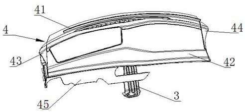
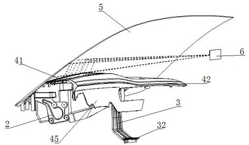
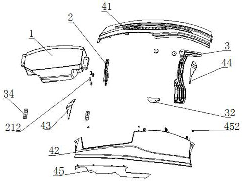
[0045] Such as Figure 1~Figure 15 , the present invention is an optical debugging vehicle platform, the optical debugging vehicle platform is refitted from a cockpit and an instrument panel of an automobile, and the automobile at least includes an A-pillar, an A-pillar panel, a cockpit, an instrument panel, and a main beam. The car platform includes an optical machine 1, a left bracket 2, a right bracket 3, a hatchback installation structure 4, a car windshield 5, and a virtual eye box position 6 behind the windshield;

[0046] The left bracket 2 includes a plate-shaped fixing portion 21 at the lower end, and the plate-shaped fixing portion is formed with a plurality of screw holes 211, and the left bracket is fixed on the A-pillar by setting bolts in the screw holes of the plate-shaped fixing portion. The upper end of the plate-shaped fixing portion extends rightward to a horizontal flange 22 with front and rear bar-shaped screw holes 221. The right bracket 3 is shaped to ma...


PUM


Abstract

The invention discloses an optical debugging vehicle platform. The optical debugging vehicle platform comprises a light machine, a left bracket, a right bracket, a hatchback type mounting structure, an automobile windshield and a virtual eye box position behind the windshield; the left bracket comprises a plate-shaped fixing part at the lower end, a plurality of screw holes are formed in the plate-shaped fixing part, and bolts are arranged in the screw holes of the plate-shaped fixing part to fix the left support on the A column; the hatchback type mounting structure comprises a front panel, a rear panel, a left side plate and a right side plate; the light machine comprises a light source unit, and a light guide unit and a diffusion unit which are arranged behind the light source unit; and the optical debugging vehicle platform further comprises a control system. The optical debugging vehicle platform is formed by refitting a vehicle cabin and an instrument desk, simultaneously adopts a hatchback type mounting structure, and is provided with the optical debugging vehicle platform, so that the road actual measurement of optical display equipment can be carried out, and the stability and the adjustability are good.

Description

technical field [0001] The invention relates to a vehicle-mounted optical display device, in particular to a car cockpit and an instrument panel refitted with a hatchback installation structure and an optical debugging vehicle platform, so that the actual road measurement of the optical display device can be carried out and the stability is good. Optical debugging vehicle platform with good adjustability. Background technique [0002] Vehicle-mounted head-up display (HUD) for short, also known as parallel display system, is currently being vigorously promoted due to its advanced assisted driving functions. [0003] Vehicle-mounted head-up display equipment is mainly composed of light source components, light guide components, free-form surface lens components, car windshields, human eye observation windows, and virtual image forming positions. Final imaging. [0004] The deficiencies in the production of existing vehicle-mounted head-up display equipment include: [0005]...

Claims


Application Information

Patent Timeline
Patent Type & Authority Applications(China)
IPC IPC(8): G01M11/00
CPCG01M11/00
Inventor 周紫军
Owner 深圳市锐思华创技术有限公司
Why Eureka
Try Eureka