Rotating equipment state monitoring index extraction method based on vibration energy gradient decomposition

A technology for vibration monitoring and rotating equipment, applied in the testing of mechanical components, testing of machine/structural components, measuring devices, etc., can solve the problems of inaccurate positioning, difficult to characterize the operating status of equipment components, and complicated calculations, and achieve real-time Monitoring, Computational Efficiency and Reliability Effects

Active Publication Date: 2021-08-31
XI AN JIAOTONG UNIV +1
View PDF8 Cites 0 Cited by
  • Summary
  • Abstract
  • Description
  • Claims
  • Application Information

AI Technical Summary

Problems solved by technology

[0003] Vibration monitoring is an effective way to monitor the operating status of rotating equipment. Traditional equipment vibration monitoring methods mainly include two types: one is based on vibration data time domain and frequency domain statistical indicators (such as peak-to-peak value, root mean square value, kurtosis index etc.), this type of monitoring method is easily affected by the interference noise in the monitoring data, and it is difficult to characterize the operating status of different parts of the equipment (such as the inner ring, outer ring and rolling element of the rolling bearing), and to realize the positioning of the weak parts of the equipment; The second is vibration monitoring based on resonance energy envelope demodulation. The effectiveness of this type of monitoring method depends on the positioning accuracy of the vibration resonance zone, and the existing resonance zone positioning methods have the defects of cumbersome calculation and inaccurate positioning. Lack of practicality and reliability in the actual equipment production process

Method used


Image

  • Rotating equipment state monitoring index extraction method based on vibration energy gradient decomposition
  • Rotating equipment state monitoring index extraction method based on vibration energy gradient decomposition
  • Rotating equipment state monitoring index extraction method based on vibration energy gradient decomposition

Examples


Embodiment Construction

[0051] Taking the monitoring of the vibration running state of a certain type of rolling bearing as an example, the present invention will be further described in detail in conjunction with the accompanying drawings and examples. The rotational frequency of the shaft where the bearing is located is 3.795 Hz, and the characteristic frequencies of each component of the bearing are shown in Table 1.

[0052] Table 1 Characteristic frequency of bearing components

[0053]

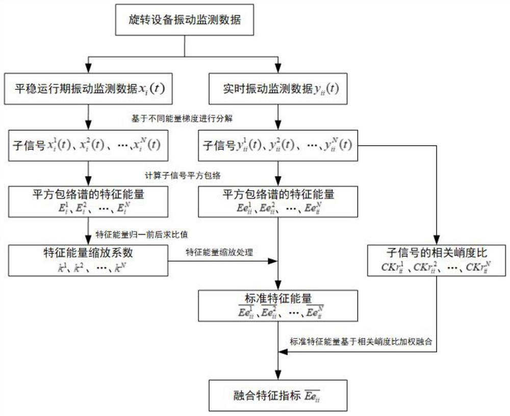
[0054] like figure 1 As shown, taking the inner ring of the rolling bearing as the monitoring object, a method for extracting the condition monitoring index of the rotating equipment based on the vibration energy gradient decomposition includes the following steps:

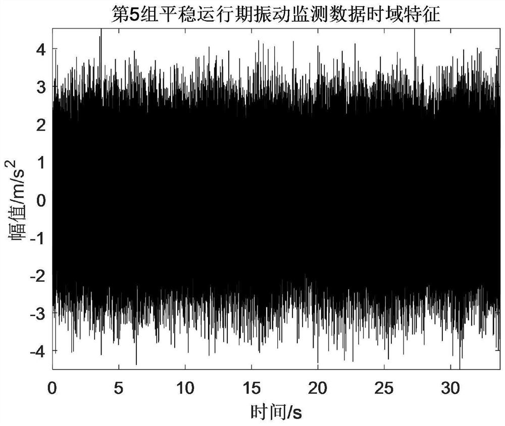
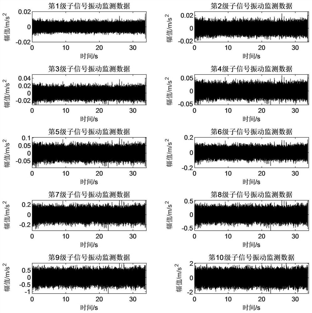
[0055] 1) Collect the first several groups of vibration monitoring data in the smooth running period of the rolling bearing inner ring, decompose the vibration monitoring data in the smooth running period into several levels of sub-signals based...


PUM


Abstract

A rotating equipment state monitoring index extraction method based on vibration energy gradient decomposition comprises the following steps: firstly, collecting a plurality of groups of vibration monitoring data in a stable operation period of rotating equipment, and decomposing the detection data into a plurality of levels of sub-signals based on different energy gradients; calculating a corresponding energy scaling coefficient according to a ratio before and after normalization of each level of sub-signal characteristic energy sequence; then collecting real-time vibration monitoring data of the rotating equipment, decomposing the monitoring data into a plurality of levels of sub-signals based on different energy gradients, and scaling the characteristic energy of a sub-signal component according to an energy scaling coefficient corresponding to each level of sub-signal; and finally, taking the correlation kurtosis ratio of the characteristic frequency of each stage of sub-signal component as a weight, carrying out weighted fusion on the sub-signals corresponding to the same group of real-time vibration monitoring data, and taking the fused characteristic energy as a rotating equipment operation state monitoring index. The method gives consideration to calculation efficiency and reliability, and achieves the operation state monitoring of the rotating equipment.

Description

technical field [0001] The invention belongs to the technical field of mechanical equipment diagnosis, and in particular relates to a method for extracting state monitoring indicators of rotating equipment based on vibration energy gradient decomposition. Background technique [0002] In the field of machinery industry, during the long-term operation of rotating equipment (bearings, gears, etc.), under the influence of alternating loads, micro-damages gradually occur in the equipment structure, and the degree of damage gradually increases with the increase of operating time, which makes the operating performance of the equipment continue to improve. The reduction will eventually lead to functional failure of the equipment, which may cause economic losses in the slightest and lead to major production safety accidents in the severest case. Therefore, in the actual production process, it is necessary to monitor the operating status of the equipment, evaluate the health status o...

Claims


Application Information

Patent Timeline
Patent Type & Authority Applications(China)
IPC IPC(8): G01M13/045G06F17/14
CPCG01M13/045G06F17/14
Inventor 王琇峰李睿郭美娜区瑞坚倪泽行
Owner XI AN JIAOTONG UNIV
Why Eureka
Try Eureka