Test system and test method of driving device
A driving device and testing system technology, applied in the field of electromechanical, can solve the problems of testing, dynamic change of load, dynamic change of motor, etc., and achieve the effect of improving comprehensiveness and reliability
- Summary
- Abstract
- Description
- Claims
- Application Information
AI Technical Summary
Problems solved by technology
Method used
Image
Examples
Embodiment 1
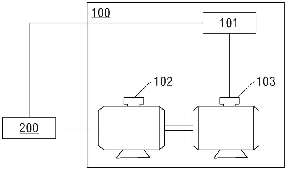
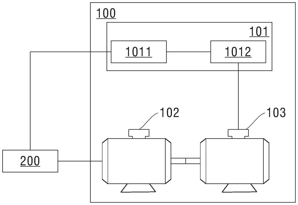
[0047] figure 1 It is a schematic diagram of a test system for a driving device provided in Embodiment 1 of the present application. see figure 1 , the test system 100 of the drive device provided in the embodiment of the present application includes: a controller 101, a test end motor 102 and a drag motor 103;
[0048] The controller 101 is respectively connected with the driving device 200 to be tested and the dragging motor 103;
[0049] The test end motor 102 is connected with the driving device 200;
[0050]The output shaft of the test end motor 102 is connected with the output shaft of the dragging motor 103;
[0051] The controller 101 sends a driving instruction to the driving device 200, so that the driving device 200 controls the test end motor 102 to rotate according to the driving instruction;
[0052] The controller 101 drives the anti-towing motor 103 to rotate, so that the anti-towing motor 103 outputs variable torque through the output shaft, so as to chang...
Embodiment 2
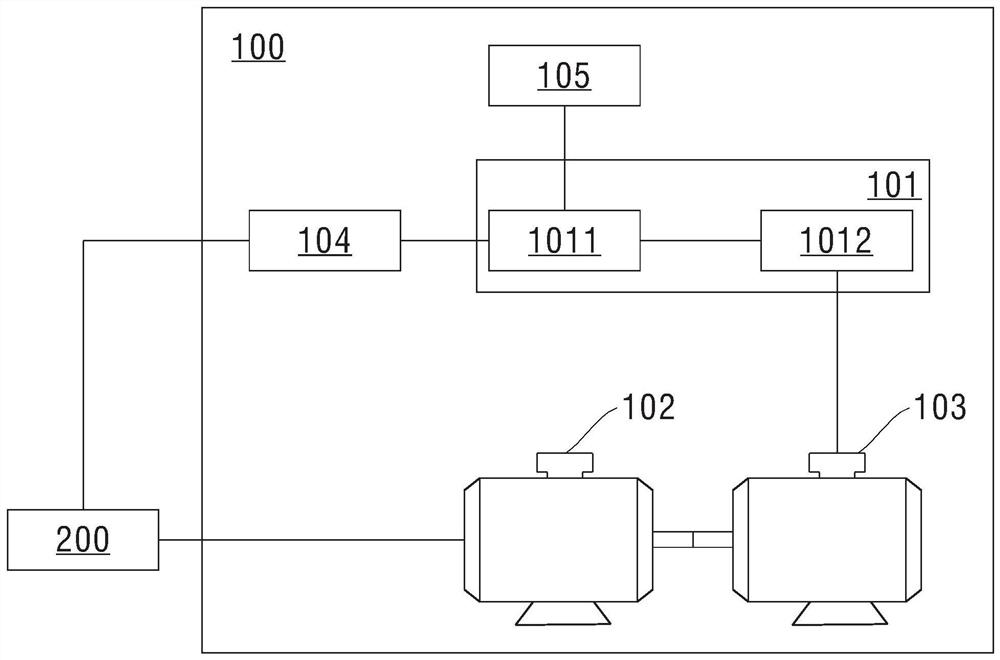
[0057] image 3 It is a schematic diagram of a test system for a driving device provided in Embodiment 2 of the present application. see image 3 The test system 100 for the driving device provided in the embodiment of the present application further includes: a programmable logic controller 104;
[0058] The programmable logic controller 104 is connected with the controller 101 and the driving device 200 respectively;
[0059] After the controller 101 sends the driving instruction to the programmable logic controller 104, the programmable logic controller 104 sends the driving instruction to the driving device 200 through the communication protocol that the driving device 200 can recognize, so that the driving device 200 Control the test end motor 102 to run.
[0060] In the embodiment of the present application, because the communication protocols used by different driving devices may be different, and the controller 101 cannot directly send driving instructions to variou...
Embodiment 3
[0083] Figure 4 It is a flow chart of a driving device testing method provided in Embodiment 3 of the present application, and the method is implemented based on the driving device testing system in Embodiment 1 or Embodiment 2 above. Unless otherwise specified, the controller involved in the following embodiments may be the controller 101 in the foregoing embodiments, and the test terminal motor involved in the following embodiments may be the test terminal motor 102 in the foregoing embodiments. The following implementation The towing motor involved in the example can be the towing motor 103 in the foregoing embodiments, and the programmable logic controller involved in the following embodiments can be the programmable logic controller 104 in the foregoing embodiments, and in the following embodiments The involved client may be the client 105 in the foregoing embodiments.
[0084] see Figure 4 , the testing method 400 of the driving device provided in the embodiment of t...
PUM
 Abstract
Description
Claims
Application Information
 - R&D
- Intellectual Property
- Life Sciences
- Materials
- Tech Scout
- Unparalleled Data Quality
- Higher Quality Content
- 60% Fewer Hallucinations
Browse by: Latest US Patents, China's latest patents, Technical Efficacy Thesaurus, Application Domain, Technology Topic, Popular Technical Reports.
© 2025 PatSnap. All rights reserved.Legal|Privacy policy|Modern Slavery Act Transparency Statement|Sitemap|About US| Contact US: help@patsnap.com


