
Optical fiber sealing interface device and manufacturing method thereof

A technology of an interface device and a manufacturing method, applied in the directions of light guides, optics, optical components, etc., can solve the problems of lack of protection of optical fibers at the interface, complicated sealing process, poor air tightness, etc., so as to avoid glue extravasation and ensure glue sealing. effect, the effect of strengthening the protection

Active Publication Date: 2021-08-31
YANGTZE OPTICAL FIBRE & CABLE CO LTD
View PDF7 Cites 0 Cited by
  • Summary
  • Abstract
  • Description
  • Claims
  • Application Information

AI Technical Summary

Problems solved by technology

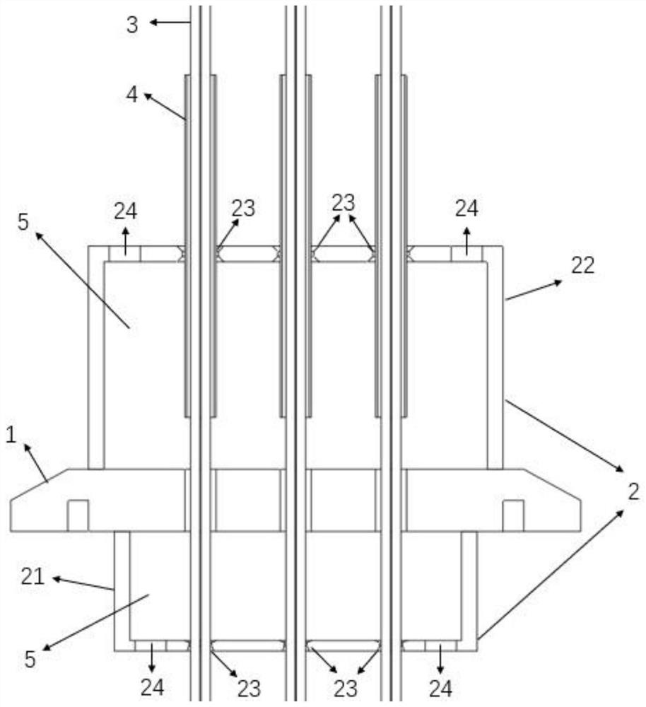
[0004] In view of the above defects or improvement needs of the prior art, the present invention provides an optical fiber airtight interface device and its manufacturing method, especially an optical fiber airtight interface device and its manufacturing method applied to low-temperature sealed containers. The inner and outer covers of the optical fiber full of glue, using the fluidity of the glue and the glue sealing volume of sufficient thickness, stabilize the gap between the glue seal interface flange, optical fiber and other accessories, thereby providing sufficient airtightness and resistance to ultra-low temperature environments , thereby solving the technical problems of poor airtightness in the prior art, lack of protection of the optical fiber at the interface and easy breakage, or complicated sealing process

Method used


Image

  • Optical fiber sealing interface device and manufacturing method thereof
  • Optical fiber sealing interface device and manufacturing method thereof
  • Optical fiber sealing interface device and manufacturing method thereof

Examples


Embodiment Construction

[0037] In order to make the object, technical solution and advantages of the present invention more clear, the present invention will be further described in detail below in conjunction with the examples. It should be understood that the specific embodiments described here are only used to explain the present invention, not to limit the present invention. In addition, the technical features involved in the various embodiments of the present invention described below can be combined with each other as long as they do not constitute a conflict with each other.

[0038] The optical fiber airtight interface device provided by the present invention is especially suitable for use in low-temperature sealed containers, including: an interface flange matched with a low-temperature sealed container, an inner protective cover and an outer protective cover respectively located on both sides of the interface flange, and an optical fiber inner protective cover. tube and / or fiber optic outer...


PUM


Abstract

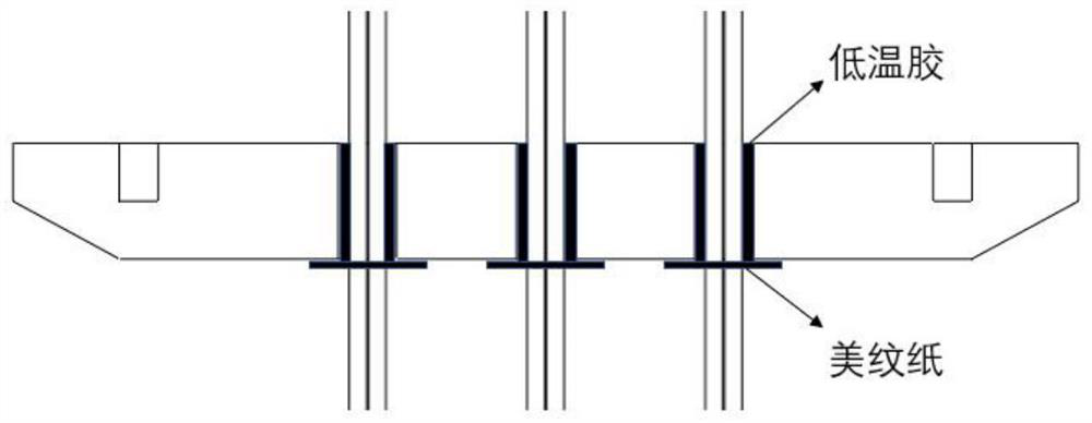
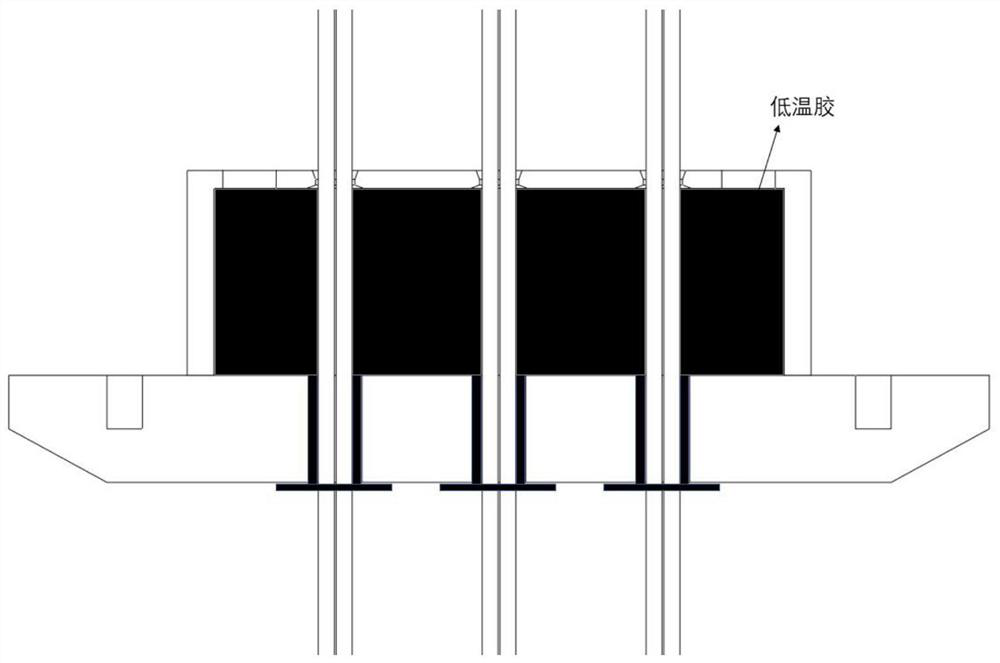
The invention discloses an optical fiber sealing interface device, which comprises an interface flange matched with a low-temperature sealing container, and an inner protective cover and an outer protective cover which are respectively positioned on two sides of the interface flange, one or more sensing optical fibers pass through the through hole in the bottom surface of the inner protecting cover, the through hole of the interface flange and the through hole of the outer protecting cover; one or more glue injection holes are formed in the bottom surface of the inner protecting cover, and one or more glue injection holes are formed in the bottom surface of the outer protecting cover; the inner space of the inner protective cover and the inner space of the outer protective cover are filled with glue. The manufacturing method comprises the following steps of: respectively assembling the interface flange fixed with the optical fiber with the inner protecting cover and the outer protecting cover to form an inner side or outer side packaging piece; and enabling the interface flange to be located in the horizontal plane, slowly injecting glue in the vertical direction through a glue injection hole in the bottom face of the inner protection cover or the outer protection cover till the inner protection cover or the outer protection cover is full of the glue, and solidifying glue sealing. According to the invention, sufficient air tightness can be provided, and a highly vacuum environment such as a superconductor low-temperature Dewar can be borne.

Description

technical field [0001] The invention belongs to the field of optical fiber sensing, and more specifically relates to an optical fiber airtight interface device and a manufacturing method thereof, in particular to an optical fiber airtight interface device applied to a low-temperature sealed container and a manufacturing method thereof. Background technique [0002] Optical fibers are mainly made of quartz glass, and optical fiber sensors that use optical fibers as transmission media and components have many excellent properties, such as: anti-electromagnetic and atomic radiation interference performance, thin diameter, soft, light weight mechanical properties ; Insulation, non-inductive electrical properties; water resistance, high temperature resistance, corrosion resistance chemical properties, etc. Therefore, it is also widely used to detect various physical quantities, that is, sensing optical fiber. In recent years, with the development of superconducting technology an...

Claims


Application Information

Patent Timeline
IPC IPC(8): G02B6/44
CPCG02B6/4459G02B6/4439G02B6/50
Inventor 杭常东李立彤陈礼庚方勇洪登熊良明
Owner YANGTZE OPTICAL FIBRE & CABLE CO LTD
Learn More