Array substrate and display panel

A technology for array substrates and display panels, which is applied to identification devices, instruments, semiconductor devices, etc., can solve problems such as the inability to increase the transmission rate of clock signal lines, difficulties in LED display screens, and technical complexity, so as to improve transmission speed and transmission efficiency, Fine screen display, the effect of increasing the number of bits

Active Publication Date: 2021-08-31
TCL CHINA STAR OPTOELECTRONICS TECH CO LTD
View PDF4 Cites 0 Cited by
  • Summary
  • Abstract
  • Description
  • Claims
  • Application Information

AI Technical Summary

Problems solved by technology

[0002] Micro-LED has developed into one of the hotspots of future display technology. Compared with the current liquid crystal display (LCD) and organic light-emitting diode (OLED) display devices, it has fast response, high color gamut, high PPI, and low energy consumption. However, it has many technical difficulties and complex technologies, especially its key technology mass transfer technology, and the miniaturization of LED particles has become a technical bottleneck, and the sub-millimeter light-emitting diode (Mini-LED) is a combination of Micro-LED and backplane. The product has the characteristics of high contrast and high color rendering performance comparable to OLED, and the cost is slightly higher than that of LCD, which is only about 60% of OLED. Compared with Micro-LED and OLED, it is easier to implement, so Mini-LED has become a major panel manufacturer. layout hotspots
[0003] At present, the backlight with a high bit (bit) number in the LED display can realize a more delicate picture display, so increasing the bit (bit) number must be the development trend of the LED display technology in the future; however, in the prior art, in the glass substrate When used, limited by the transmission rate of the clock signal line (CK), it is difficult to achieve a high bit (bit) number in the LED display.

Method used


Image

  • Array substrate and display panel
  • Array substrate and display panel
  • Array substrate and display panel

Examples


Embodiment Construction

[0028] The following will clearly and completely describe the technical solutions in the embodiments of the application with reference to the drawings in the embodiments of the application. Apparently, the described embodiments are only some of the embodiments of the application, not all of them. Based on the embodiments in this application, all other embodiments obtained by those skilled in the art without making creative efforts belong to the scope of protection of this application. In addition, it should be understood that the specific implementations described here are only used to illustrate and explain the present application, and are not intended to limit the present application. In this application, unless stated to the contrary, the used orientation words such as "up" and "down" usually refer to up and down in the actual use or working state of the device, specifically the direction of the drawing in the drawings ; while "inside" and "outside" refer to the outline of ...


PUM


Abstract

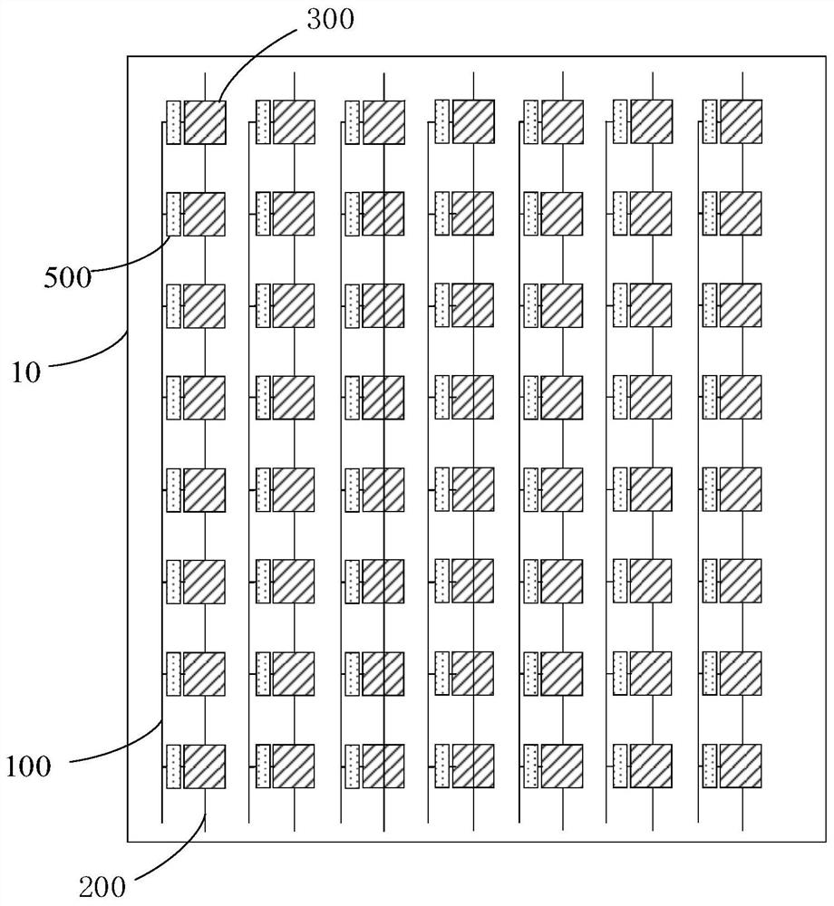
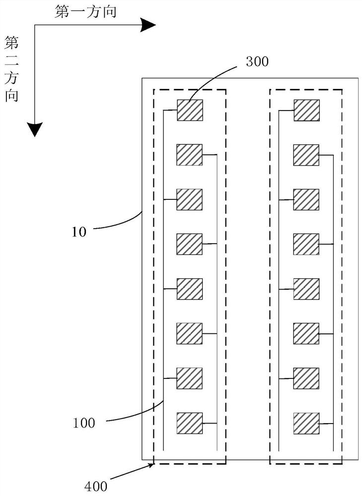
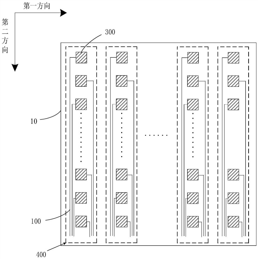
The invention discloses an array substrate and a display panel. The array substrate comprises at least two pixel unit groups arranged along a first direction and a plurality of data signal lines, each pixel unit group at least comprises two pixel units arranged along a second direction, a preset included angle is formed between the second direction and the first direction, each data signal line is at least connected with one pixel unit, and each pixel unit group is at least correspondingly connected with two data signal lines. By increasing the number of the data signal lines correspondingly connected with the pixel unit groups, the transmission speed and transmission efficiency of data can be effectively improved, the effect of increasing the bit number is achieved, and then finer and smoother picture display is achieved.

Description

technical field [0001] The present application relates to the field of display technology, and in particular to an array substrate and a display panel. Background technique [0002] Micro-LED has developed into one of the hotspots of future display technology. Compared with the current liquid crystal display (LCD) and organic light-emitting diode (OLED) display devices, it has fast response, high color gamut, high PPI, and low energy consumption. However, it has many technical difficulties and complex technologies, especially its key technology mass transfer technology, and the miniaturization of LED particles has become a technical bottleneck, and the sub-millimeter light-emitting diode (Mini-LED) is a combination of Micro-LED and backplane. The product has the characteristics of high contrast and high color rendering performance comparable to OLED, and the cost is slightly higher than that of LCD, which is only about 60% of OLED. Compared with Micro-LED and OLED, it is eas...

Claims


Application Information

Patent Timeline
IPC IPC(8): H01L25/16H01L27/15G09F9/33
CPCH01L25/167H01L27/156G09F9/33
Inventor 李艳
Owner TCL CHINA STAR OPTOELECTRONICS TECH CO LTD
Why Eureka
Try Eureka