
Control method and device of thermal printer, controller and control system.

A technology of thermal printer and control method, applied in printing device, printing, etc., capable of solving problems such as source image and target image inconsistency, resistance value deviation, etc.

Inactive Publication Date: 2021-09-03
南阳柯丽尔科技有限公司
View PDF1 Cites 3 Cited by
  • Summary
  • Abstract
  • Description
  • Claims
  • Application Information

AI Technical Summary

Problems solved by technology

Solved the current problem that the deviation of the resistance value of the print head caused the source image and the target image to be inconsistent

Method used


Image

  • Control method and device of thermal printer, controller and control system.
  • Control method and device of thermal printer, controller and control system.
  • Control method and device of thermal printer, controller and control system.

Examples


Embodiment Construction

[0051]In order to make the purpose, technical solution and advantages of the present invention clearer, the technical solution of the present invention will be described in detail below. Apparently, the described embodiments are only some of the embodiments of the present invention, but not all of them. Based on the embodiments of the present invention, all other implementations obtained by persons of ordinary skill in the art without making creative efforts fall within the protection scope of the present invention.

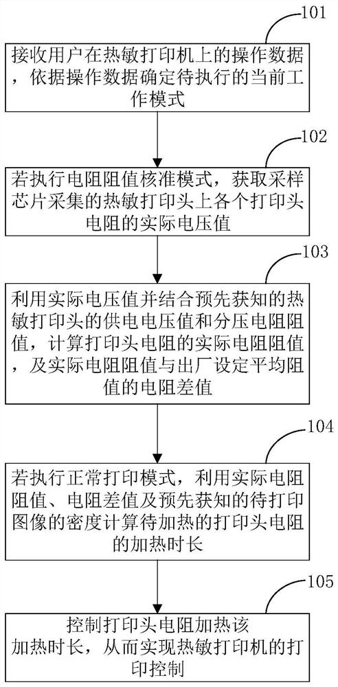
[0052] figure 1 It is a flowchart of a control method for a thermal printer provided by an embodiment of the present invention. see figure 1 , a control method for a thermal printer, comprising:

[0053] Step 101: Receive the user's operation data on the thermal printer, and determine the current working mode to be executed according to the operating data; the current working mode includes: resistance value verification mode and normal printing mode.

[0054]...


PUM


Abstract

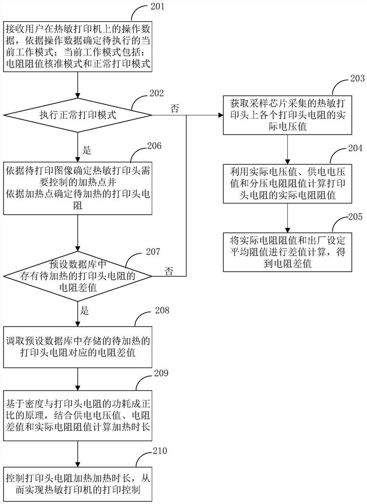
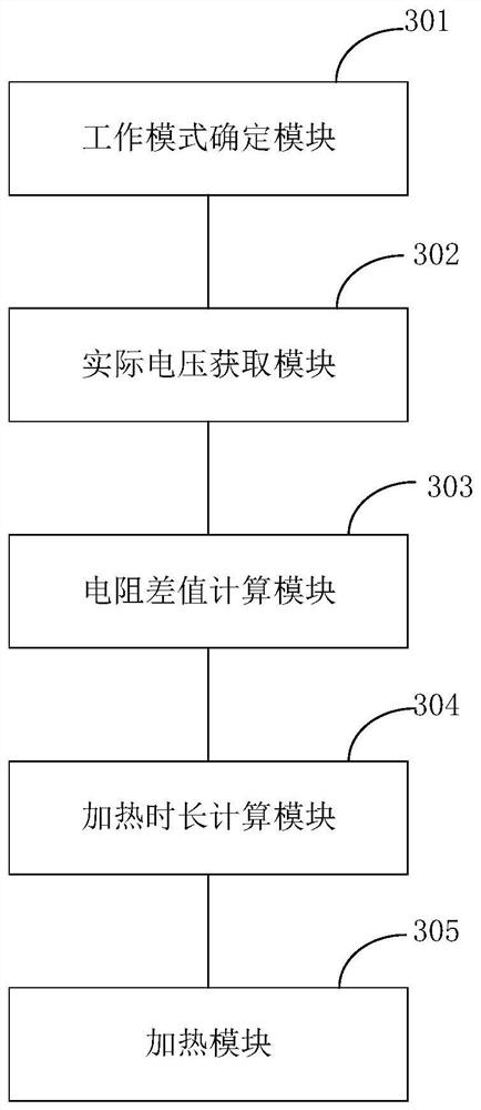
The invention relates to a control method and device of a thermal printer, a controller and a control system. The method comprises the following steps: receiving operation data of a user on the thermal printer, and determining a to-be-executed current working mode according to the operation data, where the current working mode comprises a resistance value approval mode and a normal printing mode; if the resistor resistance value approval mode is executed, obtaining the actual voltage value, collected by the sampling chip, of each printing head resistor; calculating an actual resistance value of a printing head resistor and a resistance difference value between the actual resistance value and a factory set average resistance value by utilizing the actual voltage value and combining a power supply voltage value and a divider resistance value of the thermal printing head; if the normal printing mode is executed, using the actual resistance value, the resistance difference value and the density of the to-be-printed image for calculating the heating duration of the to-be-heated printing head resistor; and controlling the heating duration of resistor heating of the printing head. According to the method, the heating duration of the printing head resistor is accurately controlled, and the error between a printed image and a source image is reduced.

Description

technical field [0001] The invention relates to the technical field of thermal printers, in particular to a control method, device, controller and control system for thermal printers. Background technique [0002] In the process of printing film, thermal printers print images onto heat-sensitive materials through the resistance heating in the thermal print head. Each minimum heating unit of the thermal print head is composed of extremely small print head resistors. However, due to the processing technology, there is a resistance value error between each print head resistor, which will directly affect the clarity of the printed target image. Spend. [0003] The current production process of the thermal print head cannot realize the effect that the resistance values ​​of the print head resistors in the thermal print head are consistent, and cannot eliminate the resistance value error. In this case, the target image will appear black or white, which will lead to the inconsist...

Claims


Application Information

Patent Timeline
Patent Type & Authority Applications(China)
IPC IPC(8): B41J2/32B41J29/393
CPCB41J2/32B41J29/393
Inventor 许统辉张斌蓝菊芳
Owner 南阳柯丽尔科技有限公司
Learn More