
A flow control method for helicopter blades

A flow control and helicopter technology, applied in the direction of motor vehicles, rotorcraft, unmanned aircraft, etc., can solve the problem that the effective control effect of the blade tip vortex cannot be achieved, the air outlet of the rotor blade is set, and the way of air outlet at the tip is not considered, etc. problem, achieve the effect of solving the problem of dynamic stall, prolonging the life of the rotor, and weakening the unsteady load

Active Publication Date: 2022-07-01
NANJING UNIV OF AERONAUTICS & ASTRONAUTICS
View PDF12 Cites 0 Cited by
  • Summary
  • Abstract
  • Description
  • Claims
  • Application Information

AI Technical Summary

Problems solved by technology

The Chinese patent with application publication number CN 108116661 A discloses an active flow control device and control method for a rotor. In this solution, an air outlet is provided on the upper surface of the rotor blade, but not at the tip of the rotor blade. The air outlet, that is to say, the scheme does not consider the way of air outlet at the tip, and cannot achieve effective control of the tip vortex

Method used

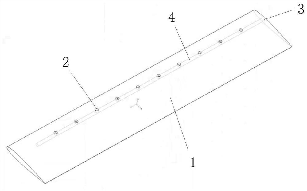
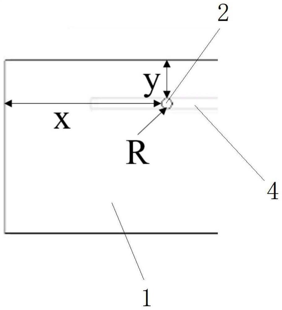
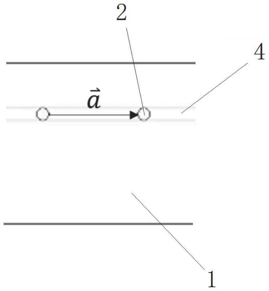

Image

  • A flow control method for helicopter blades
  • A flow control method for helicopter blades
  • A flow control method for helicopter blades

Examples


Embodiment Construction

[0035] The technical solutions in the embodiments of the present invention will be clearly and completely described below with reference to the accompanying drawings in the embodiments of the present invention. Obviously, the described embodiments are only a part of the embodiments of the present invention, but not all of the embodiments. Based on the embodiments of the present invention, all other embodiments obtained by those of ordinary skill in the art without creative efforts shall fall within the protection scope of the present invention.

[0036] The purpose of the present invention is to provide a flow control method for a helicopter blade, so as to solve the problems existing in the prior art. The operating state selects the jet from the first jet port or the jet from the second jet port. The jet through the first jet port reduces the stall effect caused by the detachment vortex, and the jet through the second jet port reduces the interference effect caused by the tip ...


PUM


Abstract

The invention discloses a flow control method for a helicopter blade. A first jet port is arranged on the upper surface of the blade, and the setting position of the first jet port and the intensity of the jet are determined according to the generation position and intensity of the detached vortex; The tip of the blade is provided with a second jet port, and the setting position of the second jet port and the strength of the jet are determined according to the generation position and intensity of the blade tip vortex; Combined with the operating state of the helicopter, it is judged that the stall effect of the detached vortex is related to the blade tip. The magnitude of the interference effect caused by the vortex; when the stalling effect of the detached vortex is large, the jet is sent out on the upper surface of the blade through the first jet port; when the tip vortex has a large interference effect, the The second jet port sends out a jet at the tip of the blade; the present invention reduces the stall effect caused by the detachment vortex through the jet at the first jet port, and reduces the interference effect caused by the tip vortex through the jet at the second jet port, And choose according to the state of the helicopter, to ensure the stability of the operation.

Description

technical field [0001] The invention relates to the technical field of flow field control of helicopter rotors, in particular to a flow control method of helicopter blades. Background technique [0002] The flow field of the helicopter rotor is complex, among which the vortex structure is the most prominent. There are complex tip vortices on the outside of the propeller disc that are continuously shedding, and the changes in the circulation at different spanwise positions of the blades will also cause vortex overflows with different intensities. In the helicopter flow field, propeller / vortex interference and vortex / vortex interference are very common due to the existence of a large number of vortices. When various disturbances occur, the aerodynamic load on the blade surface will fluctuate greatly, resulting in higher vibration and noise levels of the rotor, and even affecting the life of the helicopter. [0003] On the other hand, when the rotor is flying forward, there i...

Claims


Application Information

Patent Timeline
Patent Type & Authority Patents(China)
IPC IPC(8): B64C27/04B64C27/467B64C27/473
CPCB64C27/04B64C27/467B64C27/473B64U10/10
Inventor 招启军周旭赵国庆井思梦王博陈希
Owner NANJING UNIV OF AERONAUTICS & ASTRONAUTICS
Learn More