A positioning mechanism for a manipulator of a rotary filling machine

A positioning mechanism and filling machine technology, applied in the field of manipulators, can solve problems such as failure of capping operation, poor positioning effect of manipulators, shaking of material bottles, etc., and achieve better positioning effect, better capping effect, and better stability. Effect

Active Publication Date: 2021-10-01
HAIMEN JINHAO AUTOMATION TECH
View PDF13 Cites 0 Cited by
  • Summary
  • Abstract
  • Description
  • Claims
  • Application Information

AI Technical Summary

Problems solved by technology

[0004] The purpose of the present invention is to provide a positioning mechanism for the manipulator of the rotary filling machine, which can make the manipulator and the material bottle, the rotary worktable and the filling head perform synchronous circular motion on the one hand, while maintaining the filling method, it is also It ensures the accuracy of filling and reduces the vibration of the material bottle. On the other hand, after the material bottle is fixed, the material bottle can be rotated to flatten the internal particle raw materials and make the distribution of the particles inside the material bottle It is relatively uniform, which makes the accuracy of the capping operation better, helps to improve work efficiency, and has better practicability. It solves the problem of the existing manipulator positioning mechanism. When the material bottle is in circular motion, the positioning effect of the manipulator is usually not good , when filling, it is easy to shake the material bottle, so that the filled particles may spill out of the material bottle, and the general positioning mechanism cannot make the material bottle rotate. Due to the uncertainty of filling rate and filling angle, it is easy for particles to accumulate in the local area of ​​the material bottle, resulting in the failure of the subsequent capping operation

Method used


Image

  • A positioning mechanism for a manipulator of a rotary filling machine
  • A positioning mechanism for a manipulator of a rotary filling machine
  • A positioning mechanism for a manipulator of a rotary filling machine

Examples


Embodiment Construction

[0028] The following will clearly and completely describe the technical solutions in the embodiments of the present invention with reference to the accompanying drawings in the embodiments of the present invention. Obviously, the described embodiments are only some, not all, embodiments of the present invention. Based on the embodiments of the present invention, all other embodiments obtained by persons of ordinary skill in the art without making creative efforts belong to the protection scope of the present invention.

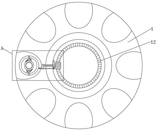
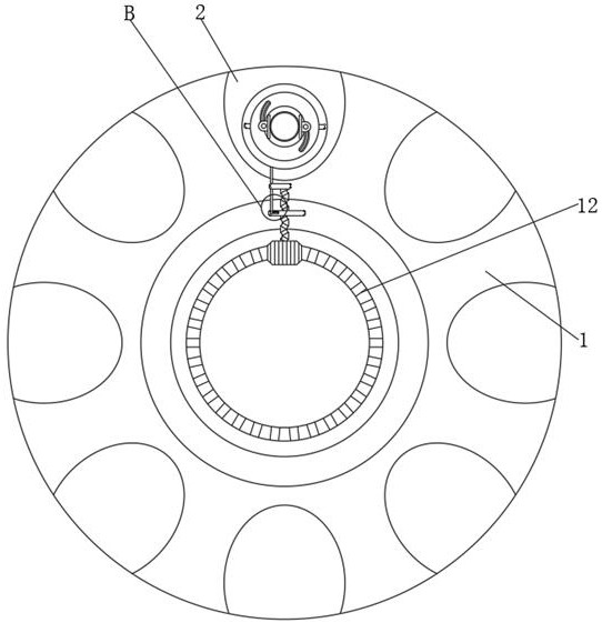
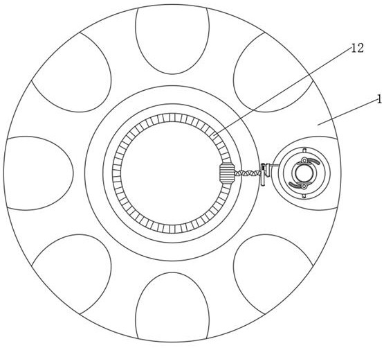
[0029] see Figure 1 to Figure 9 , the present invention provides a technical solution: a manipulator positioning mechanism for a rotary filling machine, which includes a rotary table 1 and a support block 13, and also includes a material bottle 11. The upper surface of the rotary table 1 is provided with a groove 2, Each groove 2 corresponds to a manipulator positioning mechanism, and only a single one is drawn in the figure, in order to observe the motion fo...


PUM


Abstract

The invention discloses a manipulator positioning mechanism for a rotary filling machine, which relates to the technical field of manipulators and includes a rotary workbench and a support block, and also includes a connecting part and a rotating part. Through the rotation of the rotating workbench, under the action of the connecting part , so that the rotating shaft can rotate back and forth, through which the rotating shaft can rotate back and forth, and under the action of the rotating parts, the material bottle can be rotated back and forth. On the one hand, it can make the manipulator and the material bottle, the rotary table and the filling head perform synchronous circular motion, while maintaining the filling method, it also ensures the accuracy of the filling and can reduce the shaking of the material bottle. On the one hand, after the material bottle is fixed, the material bottle can be rotated, so that the internal granular raw materials can be flattened, so that the distribution of the particles in the material bottle is more uniform, so that the accuracy of the capping operation is better, which is conducive to improving work efficiency .

Description

technical field [0001] The invention relates to the technical field of manipulators, in particular to a manipulator positioning mechanism for a rotary filling machine. Background technique [0002] The rotary filling machine is a kind of packaging machine. The rotary filling machine can be used for filling granules. When the rotary filling machine is used, the material bottle and the filling head are required to be relatively stationary, that is, the filling head and the material The bottles need to be rotated synchronously, so the manipulator is needed for positioning. [0003] At present, with the existing manipulator positioning mechanism, when the material bottle moves in a circular motion, the positioning effect of the manipulator is usually not good. When filling, the material bottle is prone to shake, causing the filled particles to spill out of the material bottle. The general positioning mechanism cannot make the material bottle rotate. When filling raw materials s...

Claims


Application Information

Patent Timeline
Patent Type & Authority Patents(China)
IPC IPC(8): B65B39/14B65B43/50B65B43/46
CPCB65B39/14B65B43/50B65B43/46
Inventor 施霞
Owner HAIMEN JINHAO AUTOMATION TECH
Why Eureka
Try Eureka