Electromagnetic regulation type energy barrier for reservoir reconstruction

A technology of reservoir reconstruction and blocker, which is applied in the field of electromagnetic regulation energy blocker, can solve the problems of insufficient impact energy of the reservoir, loss of electrical pulse excitation energy, etc. Effect

Pending Publication Date: 2021-09-03
CHINA UNIV OF PETROLEUM (EAST CHINA)
View PDF0 Cites 0 Cited by
  • Summary
  • Abstract
  • Description
  • Claims
  • Application Information

AI Technical Summary

Problems solved by technology

[0004] In the process of improving fractures in unconventional reservoirs, in order to achieve the natural frequency of the reservoir and cause reservoir resonance, it is necessary to use high voltage to generate huge electric pulse excitation to continuously impact the reservoir. However, in general reservoir gas production operations, no barrier is added. The device will cause most of the electric pulse excitation energy to be lost in the free medium, and the effective impact energy to the reservoir is not enough, so it is very necessary to install an energy blocking device

Method used


Image

  • Electromagnetic regulation type energy barrier for reservoir reconstruction
  • Electromagnetic regulation type energy barrier for reservoir reconstruction
  • Electromagnetic regulation type energy barrier for reservoir reconstruction

Examples


Embodiment 1

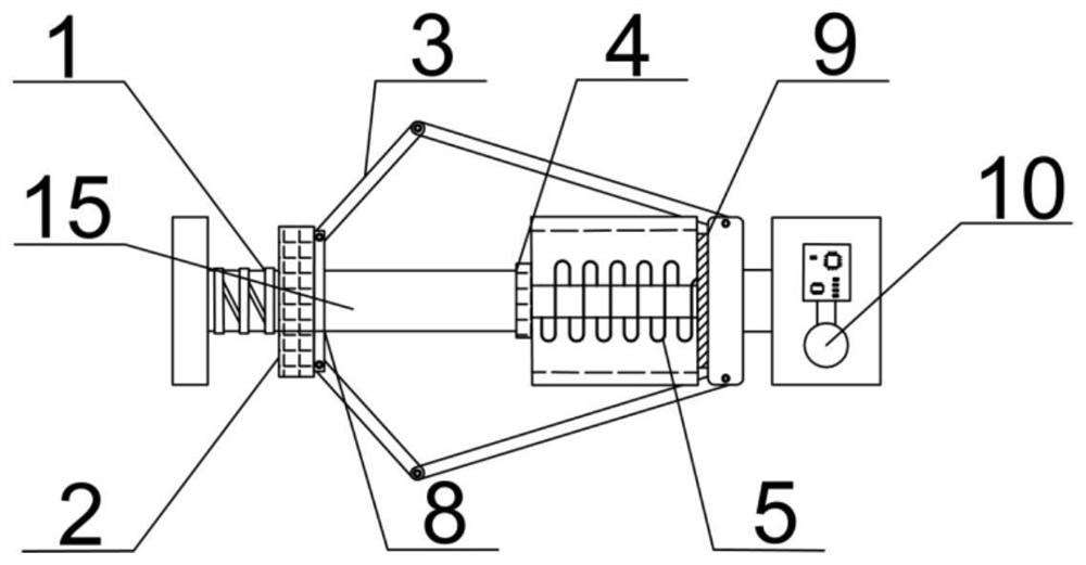
[0037] like figure 1 As shown, the radial stent 3 is connected to the permanent magnet support frame 8 and the radial stent adjustment end cover 9, and the high strength elastic film 14 is covered with the radial bracket 3, connected to the permanent magnet support frame 8 and The radial bracket 3, forms an umbrella shape; the progressive spring 1 is wound on the guide shaft 15, and the electrical module 10 is located at a separate short section, and the electromagnetic control is shorted by a joint;

[0038] like figure 2 As shown, when the permanent magnet 2 begins to be attracted by the electromagnetic core 4, the progressive spring 1 is small, ensuring the stability of the radially sliding of the permanent magnet 8, when the radial bracket 3 contacts the sleeve 13, progressive spring 1 The elastic coefficient is large, and the permanent magnet 8 stops sliding, ensuring high-strength elastic film 14 forms a sealing energy converter working medium;

[0039] The electromagnetic c...

Embodiment 2

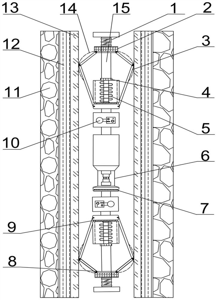
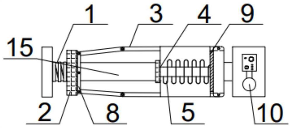
[0050] This embodiment is substantially the same as the first embodiment, such as image 3 As shown, the radial bracket 3 is not horizontally fitted when the instrument wall is fitted, and the permanent magnet support frame 8 is slaceted, since the outer permanent magnet 2 is less than the diameter of the instrument, ensuring that the instrument is never during the lower well The magnet 2, the radial bracket 3 and the high-strength elastic film 14 are not damaged; when the radial stent 3 is fitted with the instrument wall, the permanent magnet 2 and the permanent magnet support frame 8 do not contact the short section, and the progressive spring 1 is at this time. Unrestrained;

[0051] like Figure 4 As shown, when the radial bracket 3 starts closing, the progressive spring 1 is large, and the radial bracket 3 that can be pulled in the clutch sleeve 13 is closed, and when the radial stent 3 is in the instrument wall, progressive spring 1 The elastic coefficient is small, and the st...


PUM


Abstract

The invention provides an electromagnetic regulation type energy barrier for reservoir reconstruction. The electromagnetic regulation type energy barrier integrally comprises an electromagnetic control part, an energy barrier part, a permanent magnet supporting frame and a radial support adjusting end cover. The electromagnetic control part comprises a permanent magnet, an electromagnet and an electric signal control module. The energy barrier part comprises a radial support, a high-strength elastic film, a progressive spring and a guide shaft. The electromagnetic regulation type energy barrier is structurally characterized in that the electromagnet generates magnetic field force to attract the permanent magnet to do relative motion, so that the radial support is driven to stretch in the horizontal direction, and the high-strength elastic film covering the surface makes contact with a sleeve and deforms. According to the electromagnetic regulation type energy barrier in the state, an energy converter can be blocked in a small space, and the divergence loss of mechanical energy is reduced.

Description

Technical field [0001] The present invention relates to a unconventional reservoir oil gas mining apparatus, and more particularly to an electromagnetic regulatory energy barrier for reservoir transformation. Background technique [0002] my country has a very good oil and gas type, large resources, and good development prospects. In recent years, oil and gas exploration and development have made breakthroughs. In very oil and gas development, ultrasonic oil production technology, plasma pulse resonance technology, hydraulic fracturing technology, electrical pulse layer improvement technology and resonance seam technology. [0003] Among them, ultrasonic oil production technology has limitations, and ultrasonic wave is very limited in the oil layer, and it is difficult to play the effect of the reservoir of the farther distance; hydraulic fracturing technology restricts its further development of water resources, pollution and demand restrictions; electric pulses Reservoir improv...

Claims


Application Information

Patent Timeline
Patent Type & Authority Applications(China)
IPC IPC(8): E21B43/26E21B28/00
CPCE21B43/26E21B43/003E21B28/00
Inventor 康忠健邵在康高崇王聪
Owner CHINA UNIV OF PETROLEUM (EAST CHINA)
Why Eureka
Try Eureka