
Temperature and pressure cooperative control overwater photovoltaic coupling compressed carbon dioxide energy storage system and method

A technology of collaborative control and carbon dioxide, applied in the field of energy storage devices, can solve problems such as energy loss, achieve the effect of improving energy loss problems and improving regulation capabilities

Active Publication Date: 2021-09-03
SHANDONG UNIV
View PDF6 Cites 0 Cited by
  • Summary
  • Abstract
  • Description
  • Claims
  • Application Information

AI Technical Summary

Problems solved by technology

At the same time, the invention integrates the photovoltaic and energy storage system on the water, which solves the problem of energy loss caused by the photovoltaic on the water connected to the energy storage system on land

Method used


Image

  • Temperature and pressure cooperative control overwater photovoltaic coupling compressed carbon dioxide energy storage system and method
  • Temperature and pressure cooperative control overwater photovoltaic coupling compressed carbon dioxide energy storage system and method

Examples


Embodiment 1

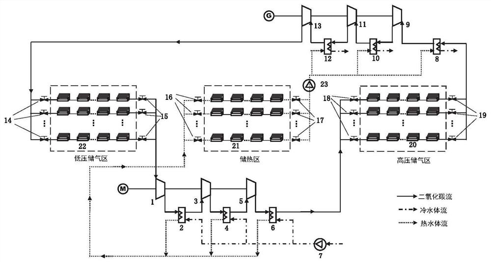
[0059] like figure 1 As shown, a water photovoltaic coupled compressed carbon dioxide energy storage system with temperature and pressure coordinated control, including a low-pressure gas storage area, a high-pressure gas storage area, a heat storage area, a heat exchanger, a compressor and an expander;

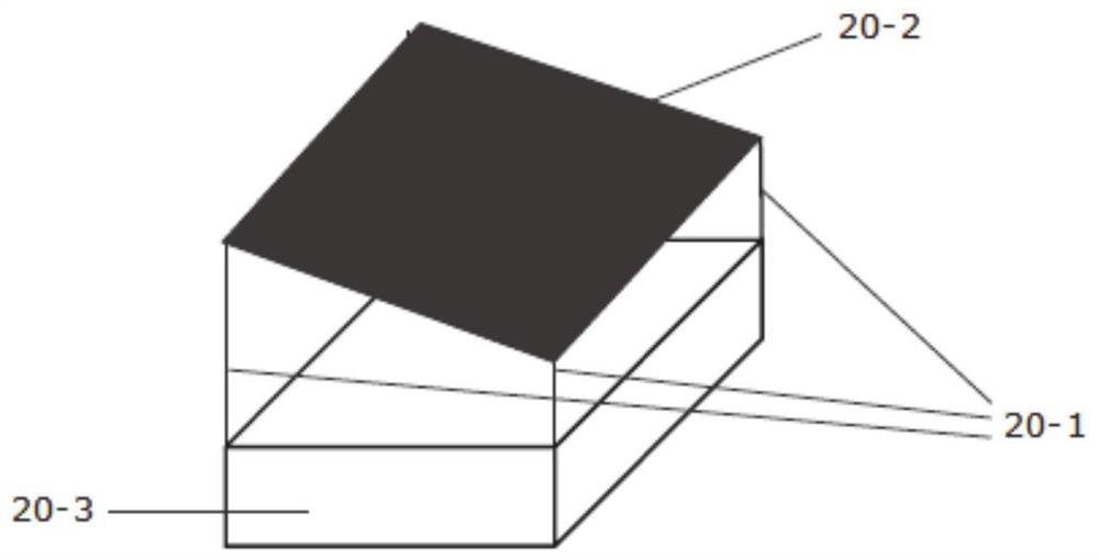
[0060] The low-pressure gas storage area, the compressor, the high-pressure gas storage area and the expander are sequentially connected; the compressor and the expander are respectively connected to a heat exchanger, and in the heat exchanger, carbon dioxide exchanges heat with water to adjust the temperature of carbon dioxide; The gas storage area is composed of multiple sets of low-pressure gas storage devices 22 connected in parallel; the high-pressure gas storage area is composed of multiple sets of high-pressure gas storage devices 20 connected in parallel.

[0061] The gas pressure in each group of low-pressure gas storage devices in the low-pressure gas storage area i...

Embodiment 2

[0070] (1) Energy storage process

[0071] When electricity consumption is underestimated, or when photovoltaic power generation is greater than its on-grid electricity, the compressed carbon dioxide energy storage system is used to consume excess electricity. First according to the formula P c =f(m c , π c ) (where P c is the compressor power, m c is the compressor flow rate, π c is the compression ratio of the compressor) and the excess power of the power grid at this time, and according to the duration of the energy storage cycle and the compression ratio of the compressor, select an appropriate low-pressure gas storage device in the low-pressure gas storage area, and open the corresponding outlet of the low-pressure gas storage area Valve 15, and select a suitable high-pressure gas storage device in the high-pressure area, open the corresponding high-pressure gas storage area inlet valve 18, so that the pressure ratio in the high-pressure gas storage device and the pr...


PUM


Abstract

The invention relates to the technical field of energy storage devices, in particular to a temperature and pressure cooperative control overwater photovoltaic coupling compressed carbon dioxide energy storage system and method. The system comprises a low-pressure gas storage area, a high-pressure gas storage area, a heat exchanger, a compressor and an expansion machine. The low-pressure gas storage area, the compressor, the high-pressure gas storage area and the expansion machine are connected in sequence. The compressor and the expansion machine are respectively connected with the heat exchanger, and carbon dioxide exchanges heat with a water body in the heat exchanger to adjust the temperature of the carbon dioxide. The low-pressure gas storage area is formed by connecting multiple sets of low-pressure gas storage devices in parallel. The high-pressure gas storage area is formed by connecting multiple sets of high-pressure gas storage devices in parallel. According to the relationship between the pressure ratio and the power and the relationship between the inlet gas temperature of the compressor and the expansion machine and the work power of the compressor and the expansion machine, the proper high-pressure gas storage devices and low-pressure gas storage devices are selected for matching and proper flow of cooling water and heating water is selected, so that smooth treatment of the photovoltaic networking power is completed, the method for cooperatively adjusting the pressure ratio and the temperature and the like is adopted, and the adjusting capability of the compressed carbon dioxide energy storage system and the like is further improved.

Description

technical field [0001] The invention relates to the technical field of energy storage devices, in particular to an aquatic photovoltaic coupled compressed carbon dioxide energy storage system and method for temperature and pressure cooperative control. Background technique [0002] The information disclosed in this Background section is only for enhancement of understanding of the general background of the invention and should not necessarily be taken as an acknowledgement or any form of suggestion that this information forms the prior art already known to a person of ordinary skill in the art. [0003] With the consumption of fossil energy and the prominence of environmental problems, photovoltaic power generation has received more and more attention. Among them, floating photovoltaics have developed rapidly because they can save land and protect water resources. However, due to the intermittency of photovoltaic power generation, it will have a great impact on the grid whe...

Claims


Application Information

Patent Timeline
IPC IPC(8): F01K7/00F01K25/10F04B37/12F04B41/02H02J3/28H02J3/38H02J15/00
CPCF01K7/00F01K25/103F04B37/12F04B41/02H02J15/006H02J3/28H02J3/381H02J2300/24Y02E70/30
Inventor 孙锲黄清喜
Owner SHANDONG UNIV
Learn More