
Engine timing system and engine timing control method

A timing control and timing system technology, applied in engine control, engine components, combustion engines, etc., can solve problems such as engine performance degradation, long time, easy wear and deformation of timing chains, etc., to avoid performance degradation and prolong life Effect

Active Publication Date: 2021-09-03
WEICHAI POWER CO LTD
View PDF6 Cites 0 Cited by
  • Summary
  • Abstract
  • Description
  • Claims
  • Application Information

AI Technical Summary

Problems solved by technology

[0004] Since the timing chain of a single structure needs to be in contact with and driven by the timing driving sprocket and the timing driven sprocket at the same time, the transmission work range is large and the time is long. The timing chain is easy to wear and deform or the tensioner is loose after a long time, which affects The service life of the timing chain, in severe cases, may even cause the chain to jump out of the chain
If the timing chain jumps teeth, it will cause engine timing errors, break the original working law of the valve mechanism, cause engine performance degradation, piston hit the valve and other failures, and in severe cases, piston scuffing and cylinder smashing may occur one after another. Failure, seriously affecting the service life of the engine

Method used

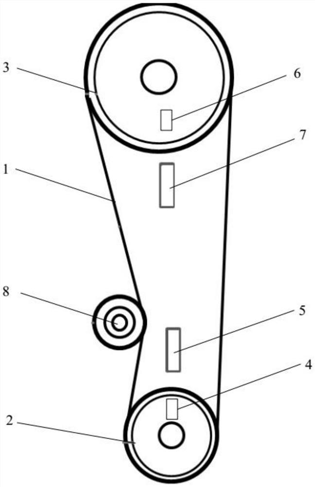

Image

  • Engine timing system and engine timing control method
  • Engine timing system and engine timing control method
  • Engine timing system and engine timing control method

Examples


Embodiment 1

[0047] When operating in the engine, the engine cylinder has been intuitive, compressed, done, and exhaust four strokes to complete the fuel combustion process. In order to ensure that the cylinder can be normally inhaled and intake, the engine timing system is required to open or close the engine's intake valve and exhaust valve.

[0048] like figure 1 As shown, this embodiment provides an engine timing system, the engine timing system includes timing transmission belt 1, the crankshaft drive wheel 2, and the cam shaft drive wheel 3, the crankshaft drive wheel 2 is set on the crankshaft and fixedly connected to it. The camshaft drive wheel 3 is disposed on the camshaft and fixed thereof, and the timing transmission belt 1 is respectively wound around the crankshaft drive wheel 2 and the cam shaft transmission. As the crankshaft rotation, the rotation of the crankshaft drive wheel 2 is rotated, and the movement of the transmission belt 1 and the rotation of the cam shaft transmiss...

Embodiment 2

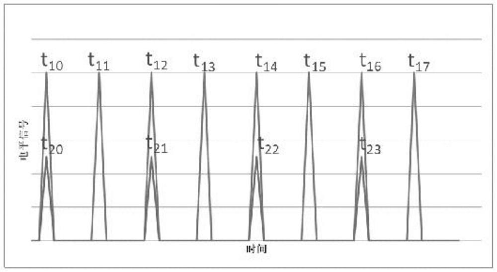
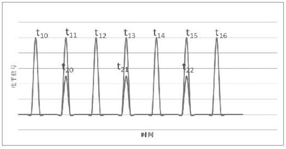
[0058] Since the sensor will issue a low level because the magnetic block is gradually rotated away from the sensor corresponding to the sensor thereof. When the magnetic block is gradually rotated in a direction adjacent to the sensor corresponding to the sensor, the sensor is high, but when the sensor can initially identify the magnetic block, the distance between the sensor and the magnetic block is relatively far, then high electricity The flat signal is relatively low; as the gear is rotated, the distance between the sensor and the magnetic block gradually decreases, and the high level signal gradually increases; when the relative position between the sensor and the magnetic block, the high level signal reaches the highest value. As the gear continues to rotate, the distance between the sensor and the magnetic block is gradually increased, and the high level signal gradually decreases. Therefore, the high level signal is specifically similar to a parabola similar to the openi...


PUM


Abstract

The invention belongs to the technical field of engines, and discloses an engine timing system and an engine timing control method. The engine timing system comprises a timing transmission belt, a crankshaft transmission wheel arranged on a crankshaft in a sleeving manner, a camshaft transmission wheel arranged on a camshaft in a sleeving manner, a first magnetic block arranged on the crankshaft transmission wheel or the crankshaft, a first sensor used for detecting the position of the first magnetic block, a second magnetic block arranged on the camshaft transmission wheel or the camshaft, and a second sensor used for detecting the position of the second magnetic block and used for judging whether the timing transmission belt has the tooth jumping fault or not according to the relative position of the crankshaft transmission wheel relative to the camshaft transmission wheel, wherein the timing transmission belt is wound around the crankshaft transmission wheel and the camshaft transmission wheel. The engine timing system can effectively recognize the rotation state of the crankshaft transmission wheel and the camshaft transmission wheel and is used for judging whether the timing transmission belt has the tooth jumping fault or not according to the relative position of the crankshaft transmission wheel relative to the camshaft transmission wheel.

Description

Technical field [0001] The present invention relates to the field of engine technology, and more particularly to an engine timing system and an engine timing control method. Background technique [0002] When the automotive engine is working, the air intake, compression, work, and exhaust gas in the cylinder, each process needs to cooperate with the motion state and position of the piston, so that intake and exhaust are coordinated with each other. To this end, the engine timing system is provided in the engine, and the driving force is passed to the camshaft under the drive of the crankshaft, the intake of the engine, the exhaust door is opened or closed when appropriate, to ensure the engine of the engine Normal inhalation and exhaust, the engine timing system acts as an intermediate bridge. [0003] Existing engine timing systems include crankshaft, intake camshaft, exhaust camshaft, timing chain, timing active sprocket, timing driven sprocket and tensioner, timing active spro...

Claims


Application Information

Patent Timeline
Patent Type & Authority Applications(China)
IPC IPC(8): F01L1/348F02D13/02
CPCF01L1/348F02D13/0203Y02T10/12
Inventor 孙善良陈翠翠王金东岳永丽
Owner WEICHAI POWER CO LTD
Learn More