Particulate trapping equipment cleaning effect evaluation method

A technology for particle capture and cleaning effect, applied in suspension and porous material analysis, instrument, permeability/surface area analysis, etc. Objective and accurate effect

Active Publication Date: 2021-09-03
SHANDONG UNIV +1
View PDF14 Cites 0 Cited by
  • Summary
  • Abstract
  • Description
  • Claims
  • Application Information

AI Technical Summary

Problems solved by technology

[0004]1. At present, the cleaning effect of the particle capture equipment has not been verified, that is, the current cleaning effect of the particle capture equipment is limited to the ventilation capacity after cleaning, However, the actual ventilation capacity of the particle capture equipment in the factory state and the relative relationship between the ventilation capacity before cleaning and the ventilation capacity after cleaning cannot be considered, and the cleaning effect of the particle capture equipment cannot be accurately verified;
[0005]2. Even if the pressure difference between the inlet end and the air outlet end of the particle capture equipment is tested by comparing before and after cleaning, the defect in the prior art is that it is used to The air flow rate for testing the cleaning effect cannot be adjusted, resulting in different types and models of particle capture equipment using a uniform flow rate for measurement. The pressure difference before cleaning and the exhaust flow data during the pressure difference test after cleaning cannot be accurately obtained Corresponding to the factory parameters of different types of particle capture equipment, the measured structure has no practical reference significance;
[0006]3. Existing test methods only test point working conditions, but in practical applications, while working continuously, the working conditions are also changing at any time, and the existing tests cannot Combined with the actual situation for comprehensive measurement, the test results are not accurate;
[0007]4. Existing test methods ignore the factory parameters of particle capture equipment, especially the relationship between the pressure difference curve and flow rate of new particle capture equipment. Direct comparison parameters cannot measure the reliability of the cleaning effect

Method used


Image

  • Particulate trapping equipment cleaning effect evaluation method
  • Particulate trapping equipment cleaning effect evaluation method
  • Particulate trapping equipment cleaning effect evaluation method

Examples


Embodiment Construction

[0090] In order to explain the overall concept of the present invention more clearly, the following will be described in detail by way of examples in combination with the accompanying drawings.

[0091] It should be noted that many specific details have been set forth in the following description so as to fully understand the present invention, but the present invention can also be implemented in other ways different from those described here, therefore, the protection scope of the present invention is not limited by the following limitations of the specific embodiments disclosed.

[0092]In addition, in the description of the present invention, it should be understood that the terms "center", "upper", "lower", "front", "rear", "left", "right", "vertical", "horizontal" ", "Top", "Bottom", "Inner", "Outer", "Axial", "Radial", "Circumferential" and other indicated orientations or positional relationships are based on the orientations or positional relationships shown in the draw...


PUM


Abstract

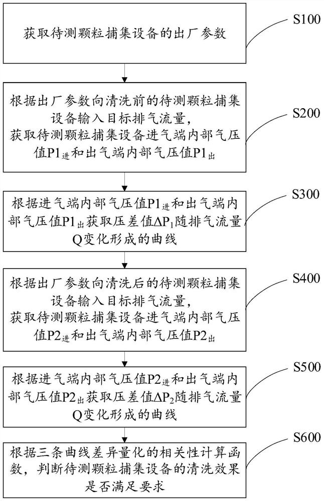
The invention relates to the field of heavy machinery aftertreatment, in particular to a particulate trapping equipment cleaning effect evaluation method which comprises the following steps: acquiring a change curve of a factory state pressure difference value of particulate trapping equipment to be detected along with exhaust flow; inputting the target exhaust flow into the to-be-detected particle trapping equipment, and obtaining a change curve of the pressure difference value of the to-be-detected particle trapping equipment along with the exhaust flow before cleaning; inputting the target exhaust flow into the to-be-detected particle trapping equipment, and obtaining a change curve of the pressure difference value of the to-be-detected particle trapping equipment after cleaning along with the exhaust flow; and judging whether the to-be-detected particle trapping equipment meets the requirement or not according to the correlation of difference quantification of the three curves. An absolute reference standard can be provided in the cleaning effect evaluation process by obtaining the factory curve of the to-be-tested particle trapping equipment. The cleaning effect is verified more objectively and accurately according to the relative curve of the factory parameters before and after cleaning.

Description

technical field [0001] The invention relates to the technical field of post-treatment of heavy machinery, in particular to a method for evaluating the cleaning effect of particle trapping equipment. Background technique [0002] Exhaust emissions from diesel engines mainly contain excessive hydrocarbons, carbon monoxide and soot particles. If the emissions are not treated and directly discharged into the outside atmosphere, serious environmental pollution will occur. In order to meet the exhaust emission requirements of large and medium-sized engineering equipment in the prior art, installing diesel particle capture equipment at the rear end of the diesel engine has become the main way for diesel engine emission control. The particulate capture equipment is mainly used to capture soot particles. During the operation of the diesel engine, the particulate capture equipment will continue to capture the soot particles emitted by the diesel engine, and gradually cover more and mo...

Claims


Application Information

Patent Timeline
Patent Type & Authority Applications(China)
IPC IPC(8): G01N7/10G01N15/08
CPCG01N7/10G01N15/0826G01N15/088
Inventor 程勇王永启孙超黄超王会营赵朋周广宇
Owner SHANDONG UNIV
Why Eureka
Try Eureka