Particle detector with particle trapping device

a particle detector and particle trapping technology, applied in the field of particle detectors, can solve the problems of condensation particle detectors not providing information on particle size, and the detection of particles using light beams is generally limited to particles over 100 nm

Inactive Publication Date: 2009-10-20
VERIONIX
View PDF10 Cites 9 Cited by
  • Summary
  • Abstract
  • Description
  • Claims
  • Application Information

AI Technical Summary

Problems solved by technology

Particle detectors using light beams generally can only detect particles that are over about 100 nm because of...

Method used


Image

  • Particle detector with particle trapping device
  • Particle detector with particle trapping device
  • Particle detector with particle trapping device

Examples


Embodiment Construction

[0015]Reference in the specification to “one embodiment” or “an embodiment” means that a particular feature, structure, or characteristic described in connection with the embodiment is included in at least one embodiment of the invention. The appearances of the phrase “in one embodiment” in various places in the specification are not necessarily all referring to the same embodiment.

[0016]It should be understood that the individual steps of the methods of the present invention may be performed in any order and / or simultaneously as long as the invention remains operable. Furthermore, it should be understood that the apparatus and methods of the present invention can include any number or all of the described embodiments as long as the invention remains operable.

[0017]While the present teachings are described in conjunction with various embodiments and examples, it is not intended that the present teachings be limited to such embodiments. On the contrary, the present teachings encompas...


PUM


Abstract

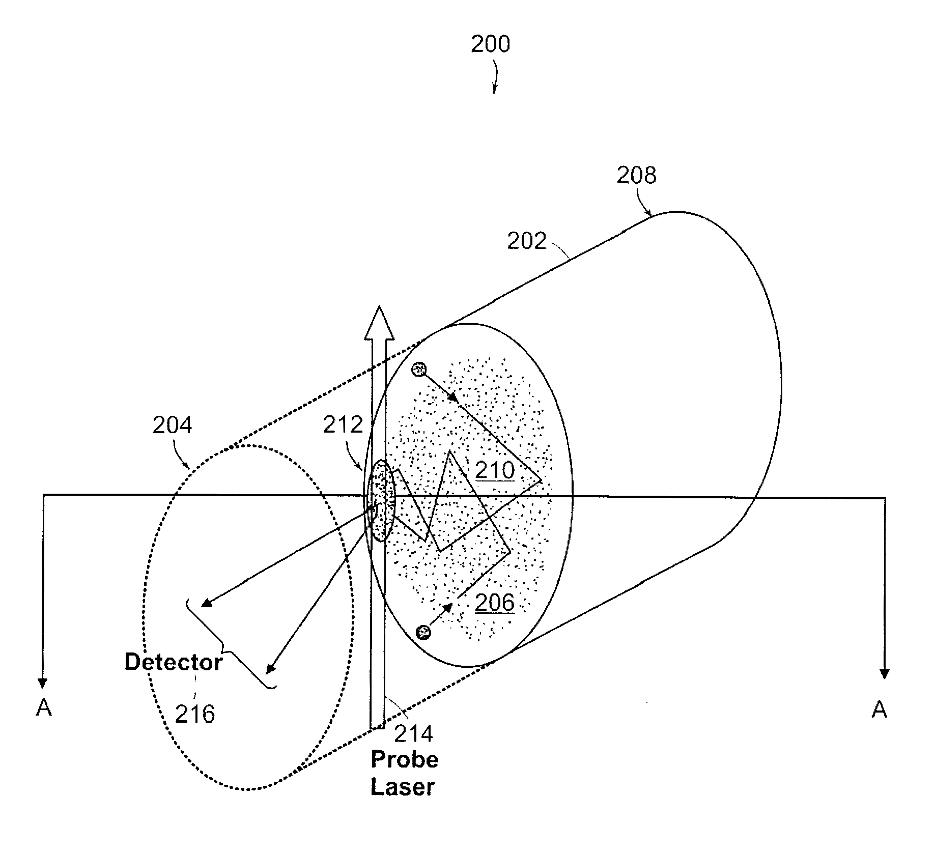
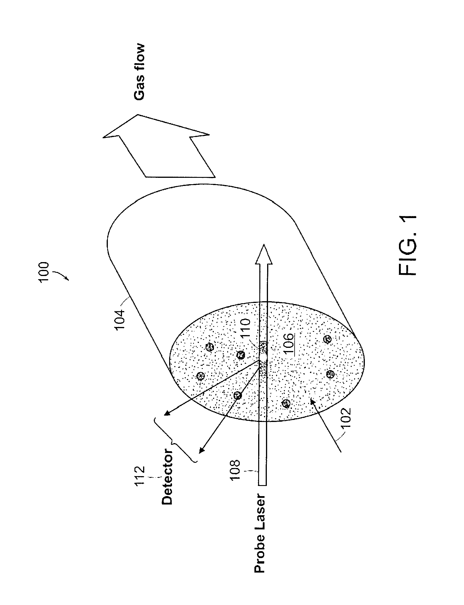
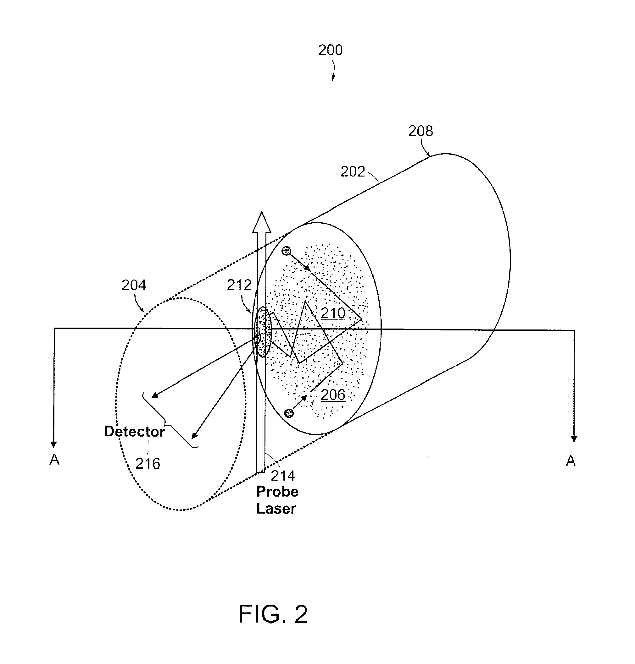
A particle detector includes an input port for receiving gas and particulate matter. A charging source generating positively and negatively charged species that charges at least some particulate matter in charging region, thereby generating a plurality of charged particles. A trapping region is formed having a potential energy minimum that attracts and confines the plurality of charged particles. A detector detects charged particles in the trapping region.

Description

RELATED APPLICATION SECTION[0001]This application claims priority to U.S. Provisional Patent Application Ser. No. 60 / 804,463, filed Jun. 12, 2006, entitled “Trapping Particle Device”, the entire application of which is incorporated herein by reference.[0002]The section headings used herein are for organizational purposes only and should not to be construed as limiting the subject matter described in the present application.BACKGROUND SECTION[0003]This invention relates generally to particle detectors. A particle is defined herein as any agglomeration of matter. Particles can include, for example, atomic species, molecular species, viruses, biological cells, and nanotubes. There are numerous types of particle detectors known in the art. One type of charged particle detector is an optical detector that uses a light beam, such as a laser, to scatter light from the particles, thereby generating a photocurrent at a detector. The resulting photocurrent waveforms are then analyzed to obtai...

Claims


Application Information

Patent Timeline
IPC IPC(8): H01J49/00G01N15/02H01J49/02H01J49/04H01J49/10
CPCH01J49/00G01N21/53G01N15/0205
Inventor DOUGHTY, CHRIS
Owner VERIONIX
Why Eureka
Try Eureka