Particle Trapping Brake Assembly With Deflector

a technology of brake assembly and deflector, which is applied in the direction of axially engaging brakes, braking systems, mechanical devices, etc., can solve the problem of unoptimum capture rate, and achieve the effect of increasing the capture ra

Inactive Publication Date: 2017-07-13
TALLANO TECH
View PDF2 Cites 8 Cited by
  • Summary
  • Abstract
  • Description
  • Claims
  • Application Information

AI Technical Summary

Benefits of technology

[0011]With these arrangements, it is possible to increase the particle capture rate under diverse aerological conditions around the brake assembly.
[0012]Specifically, one will note that the suction zone ZA is mainly located at the front of the pad relative to ...

Problems solved by technology

However, the rate of capture is not optimum because it depends on the aerological conditio...

Method used


Image

  • Particle Trapping Brake Assembly With Deflector
  • Particle Trapping Brake Assembly With Deflector
  • Particle Trapping Brake Assembly With Deflector

Examples


first embodiment

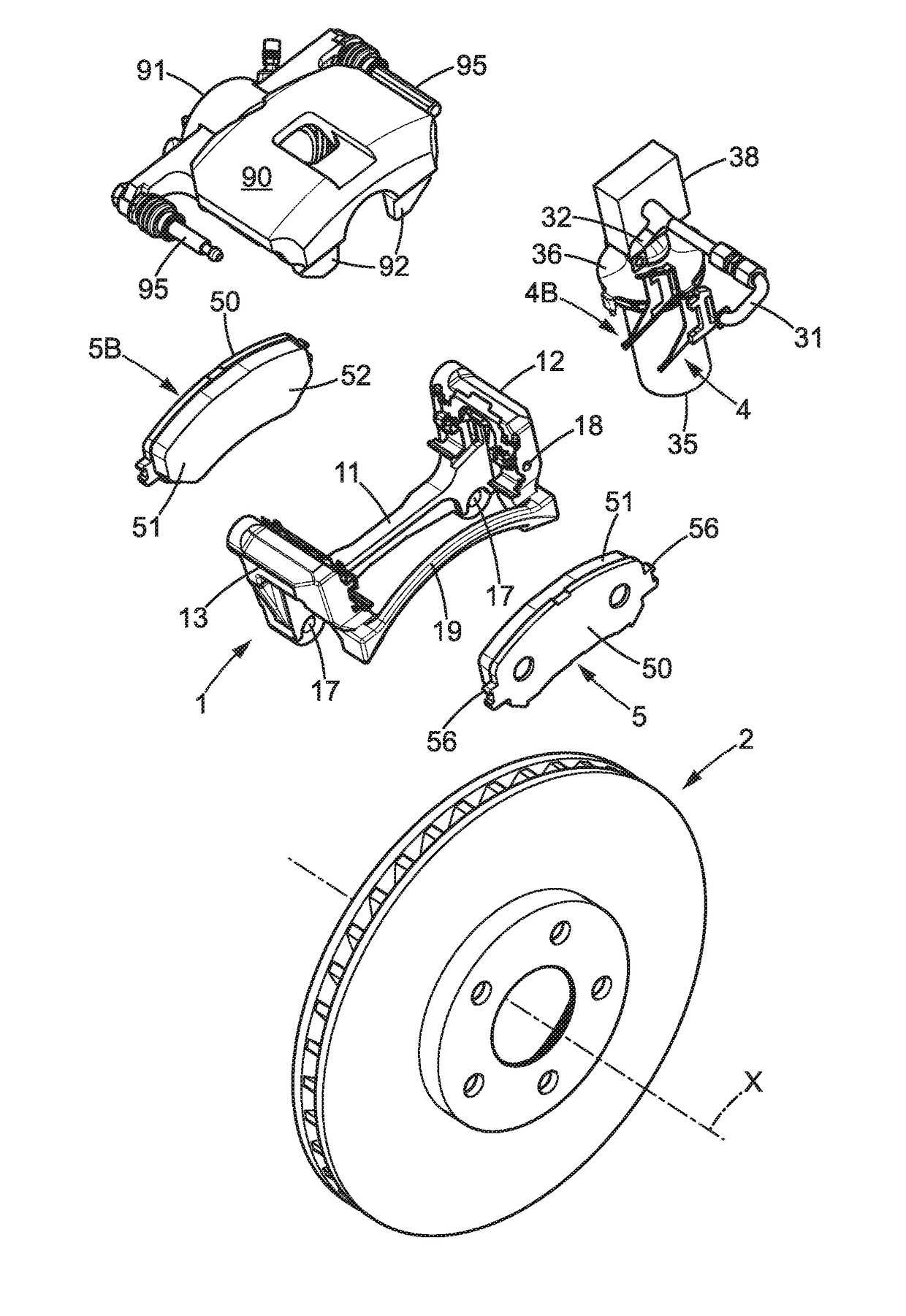
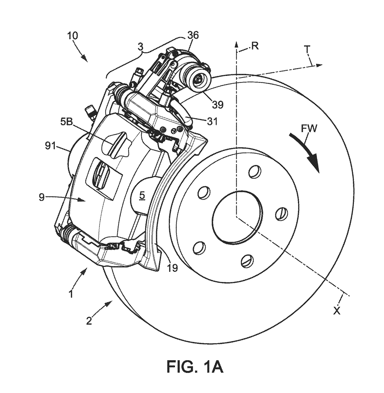
[0036]FIG. 1A shows a brake assembly 10 according to the invention which relates to a disc brake configuration. Such a disc brake configuration is very common in automobiles, utility vehicles, heavy-duty vehicles, and buses, as well as in railway rolling stock and two-wheeled vehicles. In this configuration, the braking action is applied to a rotor called a “disc” that is integral with the wheel rim but distinct from it.

[0037]There are increasing numbers of particles emitted by braking systems due to the increase in vehicular traffic, especially in urban areas. Medical studies confirm the harmfulness of these particles to the respiratory system and to health in general. It is therefore important to substantially reduce the release of these particles into the ambient environment, which is the object of the invention.

[0038]Although efforts are being made to use friction-free braking systems where possible, such as regenerative electric braking or eddy current braking, it turns out tha...

second embodiment

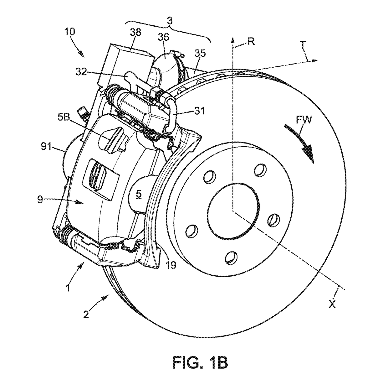
[0074] represented in FIGS. 1B and 4B, an electric motor 35 is used as the means for driving the impeller. This electric motor is controlled by a control unit (not shown) comprising software configured to activate the electric motor for example based on driver braking action on the brake pedal.

[0075]According to one variant (not shown), one uses a negative pressure generating element in a centralized unit connected by pipes to each of the brake assemblies.

[0076]In the example illustrated, the deflector 4 is a separate part made of material such as cast aluminum.

[0077]In the two embodiments illustrated, the deflectors 4, 4B are rigidly mounted with respect to the caliper bracket 1. Since the position of the caliper bracket relative to the disc is very precise, the position of the deflectors 4, 4B is properly maintained relative to the disc regardless of the degree of wear of the pad; it is thus possible to obtain a properly maintained dimension H and dimension K (see above), regardle...


PUM


Abstract

A non-polluting brake assembly comprising a caliper bracket, a rotor disc, two movable pads clamped by a caliper, the pads comprising friction material capable of releasing particles resulting from abrasion, and a suction device arranged at least partially in proximity to the caliper bracket, the suction device comprising, in proximity to each pad, a suction zone delimited by a deflector and in which a negative pressure is created, characterized in that the deflector comprises at least one portion located in an external radial position relative to the pad.

Description

TECHNICAL FIELD[0001]The present invention relates to non-polluting braking systems, particularly those intended for use in road or railway vehicles. The invention relates in particular to braking systems capable of capturing by suction the particles and dust resulting from abrasion that are emitted by friction braking.[0002]It is known that these particles are harmful to the health when released into the ambient environment. Advances in electric motors for motor vehicles have reinforced the need to treat the particles and dust resulting from the abrasion of friction brake systems.PRIOR ART[0003]Document WO2014072234 discloses a simple and fully autonomous device based on the principle of suction occurring as close as possible to the pad / disc interface.[0004]However, the rate of capture is not optimum because it depends on the aerological conditions and in particular on the relative wind prevailing in the immediate vicinity of the brake pad.[0005]There is therefore a need to improve...

Claims


Application Information

Patent Timeline
IPC IPC(8): B60T13/46F16D55/24
CPCF16D65/0031F16D2200/003F16D65/092F16D55/226F16D55/225F16D2121/04F16D55/227B60Y2200/30
Inventor ROCCA-SERRA, CHRISTOPHE
Owner TALLANO TECH
Why Eureka
Try Eureka