
Pervious concrete detection device and detection method

A technology of permeable concrete and detection device, applied in measurement device, permeability/surface area analysis, suspension and porous material analysis, etc., can solve the problems of inaccurate detection data, waste of water source, inability to detect the permeability coefficient of permeable concrete samples, etc. , to achieve the effect of convenient detection, comprehensive detection data, and improved convenience

Pending Publication Date: 2021-09-03
CHINA HYDROPOWER ELEVENTH ENG BUREAU ZHENGZHOU CO LTD +1
View PDF0 Cites 0 Cited by
  • Summary
  • Abstract
  • Description
  • Claims
  • Application Information

AI Technical Summary

Problems solved by technology

[0003] The permeable concrete system has a series of color formulas, which can be paved according to the decoration style of different environments and individual requirements. Among them, a large number of such permeable concrete will be used in paving roads in parks, which can improve the aesthetics and prevent water accumulation on the road. Pervious concrete needs to be used during production To test its water permeability, the current testing equipment can only detect horizontal permeable concrete samples, but the terrain in the park is uneven, and the paved permeable concrete roads have various slopes, so it is impossible to detect the permeable concrete samples at various angles. Part of the water permeability coefficient makes the test data inaccurate, and when the permeable concrete tester is used to test the water permeability of the permeable concrete, the water will flow directly to the ground, resulting in waste of water sources, and some bonds on the permeable concrete are unstable The debris and impurities in pervious concrete may be washed down by water, which is not conducive to recycling. Therefore, it is necessary to provide a new detection device and detection method for pervious concrete to meet the needs of users.

Method used


Image

  • Pervious concrete detection device and detection method
  • Pervious concrete detection device and detection method
  • Pervious concrete detection device and detection method

Examples


Embodiment

[0040] In order to make the purpose, technical solution and advantages of the present invention clearer, the following will further describe the implementation of the present invention in detail in conjunction with the accompanying drawings.

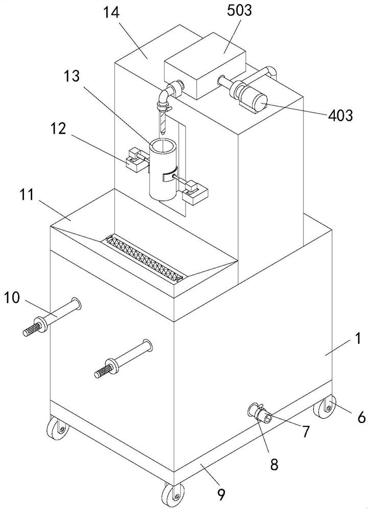
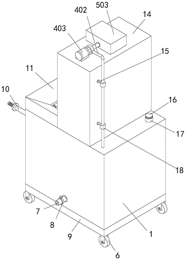
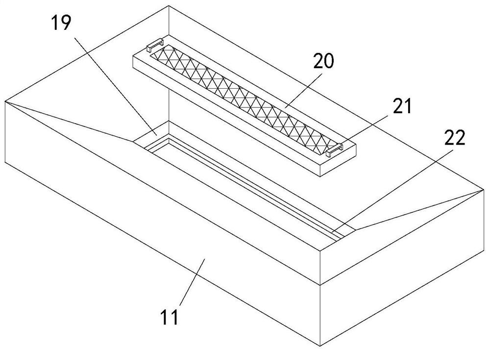
[0041] Such as Figure 1-7 As shown, a detection device for permeable concrete includes a water tank 1, the top of the water tank 1 is fixedly connected with a mounting base 14, the front side of the mounting base 14 is fixedly connected with two fixing blocks 12, and the front side of the mounting base 14 is provided with a detection Sleeve 13, a rotating block 24 is connected to the top of the fixed block 12, and the opposite sides of the two rotating blocks 24 are fixedly connected with the clamping mechanism 2 used in conjunction with the detection sleeve 13, and the inside of the detection sleeve 13 is placed with concrete Block 28, the top of mounting seat 14 is fixedly connected with the water storage mechanism 5 that cooperates w...


PUM


Abstract

The invention belongs to the technical field of pervious concrete detection, and particularly relates to a pervious concrete detection device which comprises a water tank. A mounting seat is fixedly connected to the top of the water tank, two fixing blocks are fixedly connected to the front side of the mounting seat, a detection sleeve is arranged on the front side of the mounting seat, and rotating blocks are connected to the tops of the fixing blocks. The opposite sides of the two rotating blocks are fixedly connected with clamping mechanisms matched with the detection sleeve for use, a concrete block is placed in the detection sleeve, and the top of the mounting seat is fixedly connected with a water storage mechanism matched with the concrete block for use. The problems that according to the existing pervious concrete detection device and the detection method, detection data are inaccurate due to the fact that permeation coefficients of all parts of a pervious concrete sample at various angles cannot be detected, and water directly flows to the ground when the pervious concrete detector is used for detecting the water permeability of pervious concrete, and water sources are wasted are solved.

Description

technical field [0001] The invention relates to the technical field of permeable concrete detection, in particular to a detection device and a detection method for permeable concrete. Background technique [0002] Permeable concrete, also known as porous concrete, sand-free concrete, and permeable floor, is a porous lightweight concrete made of aggregate, cement, reinforcing agent, and water. It does not contain fine aggregate, and permeable concrete is composed of coarse The surface of the aggregate is covered with a thin layer of cement slurry bonded to each other to form a honeycomb structure with uniform distribution of pores, so it has the characteristics of air permeability, water permeability and light weight. This pavement material can allow rainwater to flow into the ground, effectively replenish groundwater, and relieve Some urban environmental problems, such as the sharp drop in the groundwater level of the city, can effectively eliminate the hazards of environmen...

Claims


Application Information

Patent Timeline
Patent Type & Authority Applications(China)
IPC IPC(8): G01N15/08
CPCG01N15/08G01N15/0806
Inventor 陈文娟夏海军吴昊景若婷宋淑阳
Owner CHINA HYDROPOWER ELEVENTH ENG BUREAU ZHENGZHOU CO LTD
Learn More