An integrated hybrid electrical cabinet that can adjust exhaust volume based on calorific value

An integrated technology with exhaust volume, applied in the direction of electrical equipment shell/cabinet/drawer, electrical components, photovoltaic power generation, etc., can solve the problems of heating of electrical components and uneven heat dissipation effect of electrical cabinets

Active Publication Date: 2022-07-08
SHENHENG ELECTRIC EQUIP CO LTD
View PDF6 Cites 0 Cited by
  • Summary
  • Abstract
  • Description
  • Claims
  • Application Information

AI Technical Summary

Problems solved by technology

[0004] The purpose of the present invention is to provide an integrated hybrid electrical cabinet that can control the size of the exhaust port according to the installation requirements of electrical components, and can adjust the exhaust volume based on the calorific value. The heat dissipation effect of the electrical cabinet is uneven, which may easily cause serious heating problems of the internal high-voltage electrical components

Method used


Image

  • An integrated hybrid electrical cabinet that can adjust exhaust volume based on calorific value
  • An integrated hybrid electrical cabinet that can adjust exhaust volume based on calorific value
  • An integrated hybrid electrical cabinet that can adjust exhaust volume based on calorific value

Examples


Embodiment 1

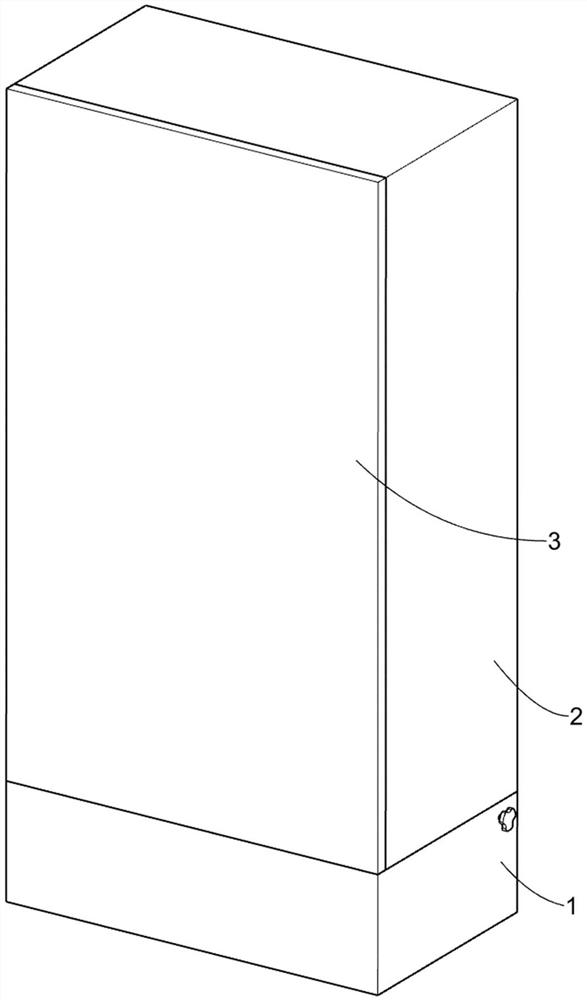
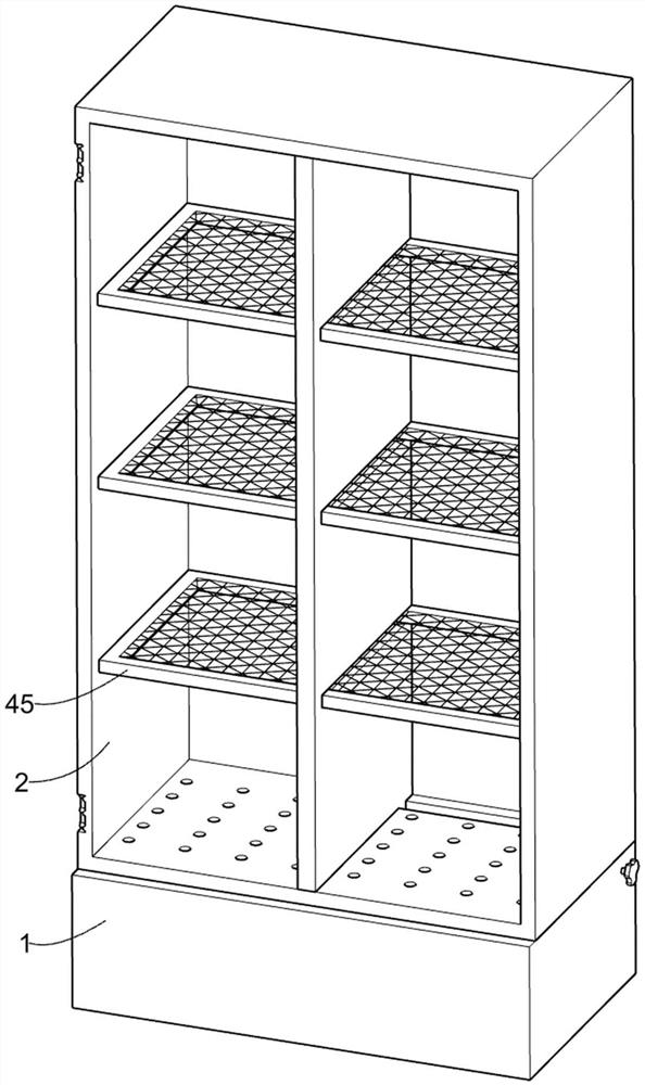
[0034] An all-in-one hybrid electrical cabinet that can adjust the exhaust volume based on the calorific value, such as Figure 1-15 As shown, it includes a bottom frame 1, a box body 2, a cover plate 3, an adjustment assembly 4, an air inlet expansion assembly 5, a speed change assembly 6 and an air extraction assembly 7. The bottom frame 1 has two exhaust ports, and the bottom frame 1 The box body 2 is fixedly installed on the top, and the bottom of the box body 2 has a plurality of heat dissipation holes. The box body 2 is connected with a cover plate 3 through hinges. The adjustment component 4 for adjustment is arranged on the box body 2, and the air inlet expansion component 5. It is slidably connected in the bottom frame 1, the speed change assembly 6 is arranged on the inner bottom of the bottom frame 1, and the inner wall of the bottom frame 1 is fixedly installed with an air extraction assembly 7 for extracting the hot air generated by the internal electrical componen...

Embodiment 2

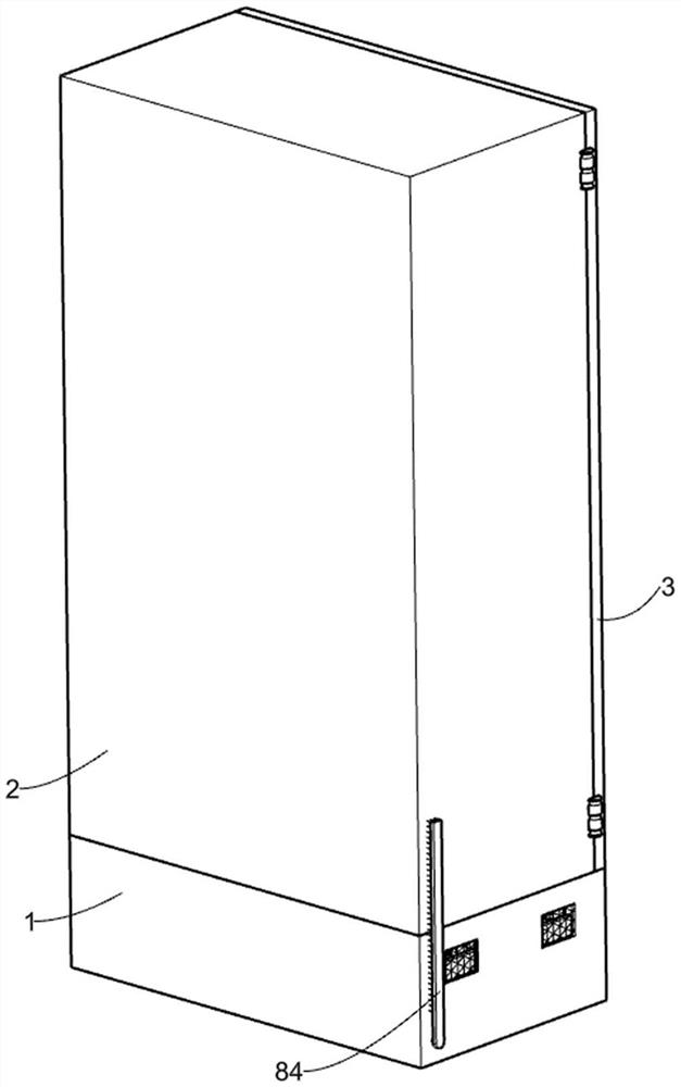
[0042] On the basis of Example 1, as Figure 11 , Figure 16 As shown, it also includes a cleaning assembly 8, the speed change assembly 6 is provided with a cleaning assembly 8, and the cleaning assembly 8 is used to scrape off the sticky dust on the exhaust port on the bottom frame 1, and the cleaning assembly 8 includes a The second transmission shaft 801 , the universal joint transmission shaft 802 , the drive plate 81 , the connecting shaft 82 , the slotted swing rod 83 and the brush plate 84 , the inclined surface guide plate 61 is rotatably connected with the second transmission shaft 801 , the second transmission shaft The universal drive shaft 802 is fixed on the 801, the universal drive shaft 802 away from the second drive shaft 801 is welded to one end of the first drive shaft 612, and the end of the second drive shaft 801 away from the universal drive shaft 802 is welded with a drive plate 81. , the bottom frame 1 is rotatably connected with a connecting shaft 82,...


PUM


Abstract

The invention relates to an integrated hybrid electrical cabinet, in particular to an integrated hybrid electrical cabinet that can adjust the exhaust volume based on the heat generation, including a bottom frame, a box body, a cover plate, an adjustment component, an air inlet expansion component, etc. ; There are two exhaust ports on the bottom frame, a box body is fixedly installed on the top of the bottom frame, a plurality of heat dissipation holes are arranged at the bottom of the box body, a cover plate is connected to the box body through hinges, the adjustment components are arranged on the box body, and the air inlet The expansion component is slidably connected in the bottom frame. Push the lower pressure rod and the combined baffle plate to move downward through the inclined plate, and the combined baffle plate opens the exhaust port on the bottom frame. Gas volume purpose.

Description

technical field [0001] The present invention relates to an integrated hybrid electrical cabinet, in particular to an integrated hybrid electrical cabinet capable of adjusting the exhaust gas volume based on heat generation. Background technique [0002] There are various electrical components and circuits in the electrical cabinet. The electrical cabinet is made of steel and is used to protect the electrical components and circuits from working properly. The electrical cabinet is used in situations where the load is relatively scattered and there are few circuits. It is widely used in chemical industry, power system, metallurgical system, nuclear power industry, fire safety monitoring and transportation industry. [0003] In the existing electrical cabinet, it is usually made into a box with a relatively closed internal space. In order to prevent heat accumulation in the electrical cabinet and high temperature, it is necessary to open heat dissipation through holes around th...

Claims


Application Information

Patent Timeline
Patent Type & Authority Patents(China)
IPC IPC(8): H05K5/02H05K7/20B08B1/04B08B1/00
CPCH05K5/0213H05K5/0217H05K7/20209H05K7/20145B08B1/04B08B1/002Y02E10/50
Inventor 旷文祥
Owner SHENHENG ELECTRIC EQUIP CO LTD
Why Eureka
Try Eureka