
Eureka
For R&D, Eureka makes reading and utilizing patents & technical documents easy.
Eureka AIR
Designed for self-driven R&D workflows. Generate viable solutions, solve complex R&D challenges, empower your innovation with AI.

Eureka Materials
Designed for material experts only. Revolutionize your material R&D, from search, analyze, to developing new materials.

TechResearch
Generate reliable direction feasibility study reports for your R&D in just a few steps.

TechSeek
Discover and master advanced knowledge NOW. Basics, ideas, possibilities, all at once.

TechMind
As an expert in R&D Theories, TechMind can generates customized viable solutions instantly.

TechRisk
Analyze your overall solution with one click, know your potential R&D risks in advance.

TechMonitor
Get weekly tech updates, stay abreast of the latest tech innovations and key insights.
Sealing clamping mechanism
A clamping mechanism and clamping component technology, applied in coatings, devices for applying liquid to surfaces, etc., can solve problems such as uneven distribution of clamping force, uncontrollable clamping force, etc., to get rid of limitations, clamp The effect of uniform tightening and prevention of glue contamination
- Summary
- Abstract
- Description
- Claims
- Application Information
AI Technical Summary
Problems solved by technology
Method used
Image

Examples
Embodiment 1
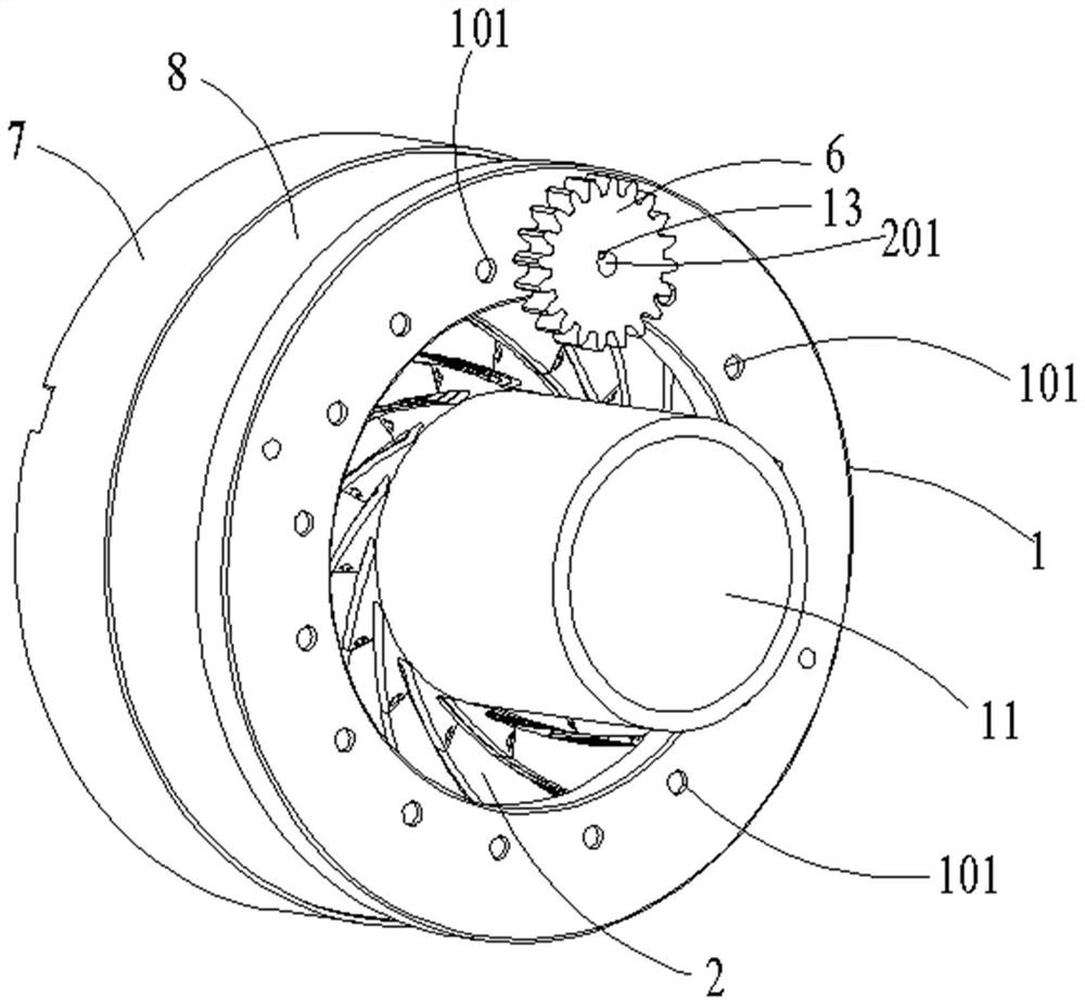
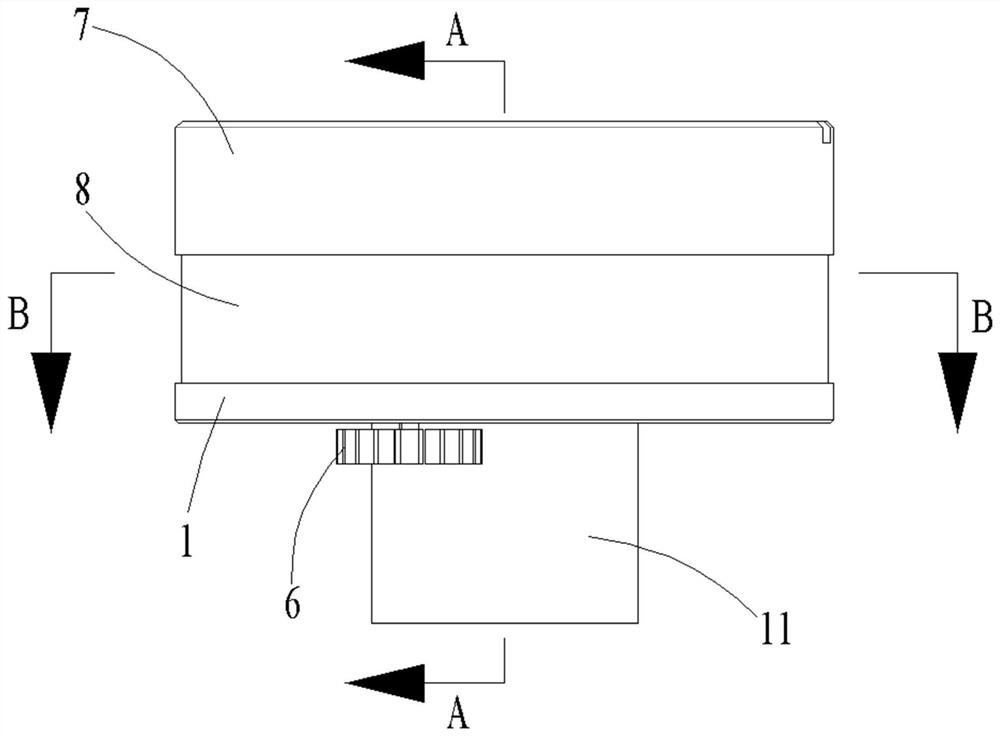
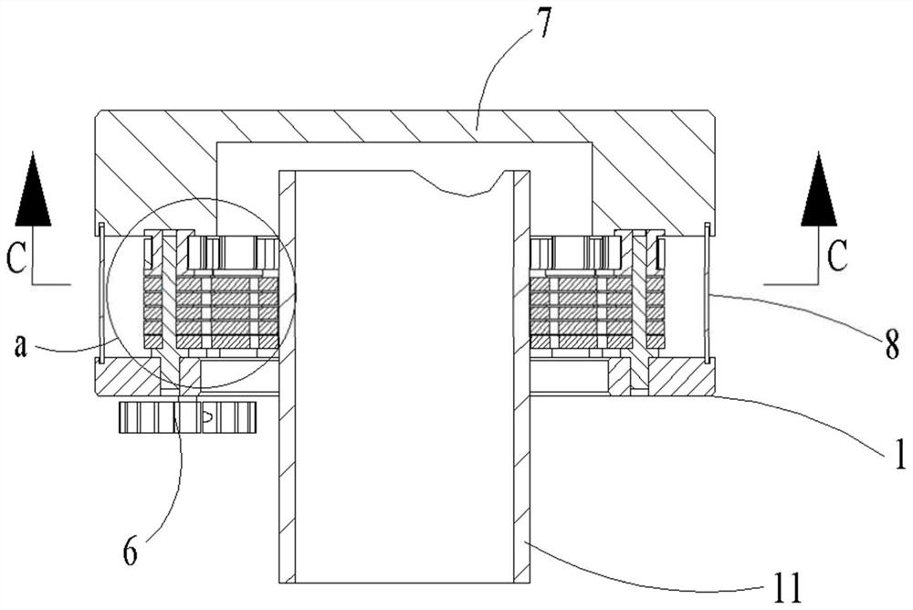
[0036] Such as Figure 1-Figure 4 As shown, a sealing clamping mechanism, including:
[0037] The fixed chuck 1 is an annular disc, the end face of the fixed chuck 1 is used to install the clamping assembly 2, and a through hole 101 is formed in the center of the annular disc for passing through the tubular workpiece 11, The diameter of the through hole 101 can be equal to the diameter of the workpiece 11 or larger than the diameter of the workpiece 11 .
[0038] There are sixteen clamping assemblies 2 arranged in a circular array on the fixed chuck 1, including a support rod 201, a clamping jaw 202 driven by the support rod 201 and a synchronous pulley 203, and the support rod 201 is rotationally connected with the fixed chuck 1 , the support rod 201 is composed of a cylindrical section 2011 and a prism section 2013, the cross section of the prism section 2013 is rectangular, and the fixed chuck 1 is provided with sixteen shaft holes 12 in a circumferential array, and the cy...
Embodiment 2
[0045] If the jaws 202 extend in the same direction from the end close to the support rod 201 to the end far away from the support rod 201, it will cause the free end sides of the adjacent jaws 202 to squeeze each other, and a larger initial force is required at this time. Only then can the jaws 202 be opened and separated, and the jaws 202 cannot be evenly opened. For this reason, the structure of the jaws 202 is improved in this embodiment. Specifically, the free end of the jaws 202 has a direction of rotation toward the jaws 202. Extended hook portion 15. The tightening rotation direction of the clamping jaw 202 refers to the rotation direction of the clamping jaw 202 during the tightening process of the mechanism, such as Figure 7 As shown, the extension direction of the hook portion 15 is opposite to the direction of the tip of the free end of the jaw 202, and the hook portion 15 is used to connect with the tip of the adjacent jaw 202, which can avoid the side walls of t...
Embodiment 3
[0047] In this embodiment, the clamping jaw 202 is changed from a rigid material to a flexible material, for example, rubber material or PTEE material, etc. can be used. The deformation can better realize the surface contact, and the clamped product can also be polygonal, which gets rid of the limitations of the traditional clamping mechanism.
[0048] In order to reduce maintenance costs, the jaws 202 in this embodiment preferably adopt a quick-change split structure, such as Figure 5 and Figure 7 As shown, the jaw 202 is composed of a brake blade 2021 and a sealing blade 2022, the brake blade 2021 is connected with the support rod 201, the sealing blade 2022 is connected with the brake blade 2021, and the ends of several sealing blades 2022 are suitable to form a closed column Mounting surface 5. At this time, it is only necessary to make the sealing blade 2022 of a flexible material. When the sealing blade 2022 is worn out, only the sealing blade 2022 needs to be replac...
PUM
 Abstract
Description
Claims
Application Information
 - R&D Engineer
- R&D Manager
- IP Professional
- Industry Leading Data Capabilities
- Powerful AI technology
- Patent DNA Extraction
Browse by: Latest US Patents, China's latest patents, Technical Efficacy Thesaurus, Application Domain, Technology Topic, Popular Technical Reports.
© 2024 PatSnap. All rights reserved.Legal|Privacy policy|Modern Slavery Act Transparency Statement|Sitemap|About US| Contact US: help@patsnap.com