Reamer mechanism for cutter suction dredger

A technology of cutter suction boat and reamer, which is applied in the direction of earth mover/shovel, mechanically driven excavator/dredger, construction, etc. It can solve the problems of affecting the excavation effect, damage of reamer blade, wear of reamer teeth, etc. , to achieve the effect of maintaining excavation effect, improving work efficiency and good excavation effect

Active Publication Date: 2021-09-07
MINGGUANG CITY LIUXIANG PUMP IND
View PDF4 Cites 0 Cited by
  • Summary
  • Abstract
  • Description
  • Claims
  • Application Information

AI Technical Summary

Problems solved by technology

[0004] In the prior art, multiple reamer teeth are often fixed on the reamer blade of the cutter suction marine reamer mechanism to increase the sharpness during excavation. Due to the nature of the work, long-term use will cause serious wear or loss of the reamer teeth. Hard objects such as hard rocks are deformed when they are hit by hard objects, so the reamer teeth must be replaced regularly. In order to facilitate replacement, most reamer teeth are detachable on the reamer blade. Due to cost or laziness and dereliction of duty, it is often not timely to replace the reamer teeth that are already in poor condition, resulting in excessive wear of the reamer teeth and a decrease in work efficiency, thereby affecting the actual excavation effect, and even causing further damage to the reamer blade.

Method used


Image

  • Reamer mechanism for cutter suction dredger
  • Reamer mechanism for cutter suction dredger
  • Reamer mechanism for cutter suction dredger

Examples


Embodiment Construction

[0031] In order to enable those skilled in the art to better understand the technical solutions of the present invention, the present invention will be further described in detail below in conjunction with the accompanying drawings.

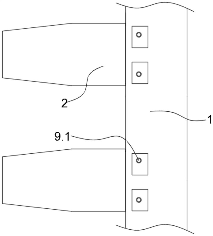
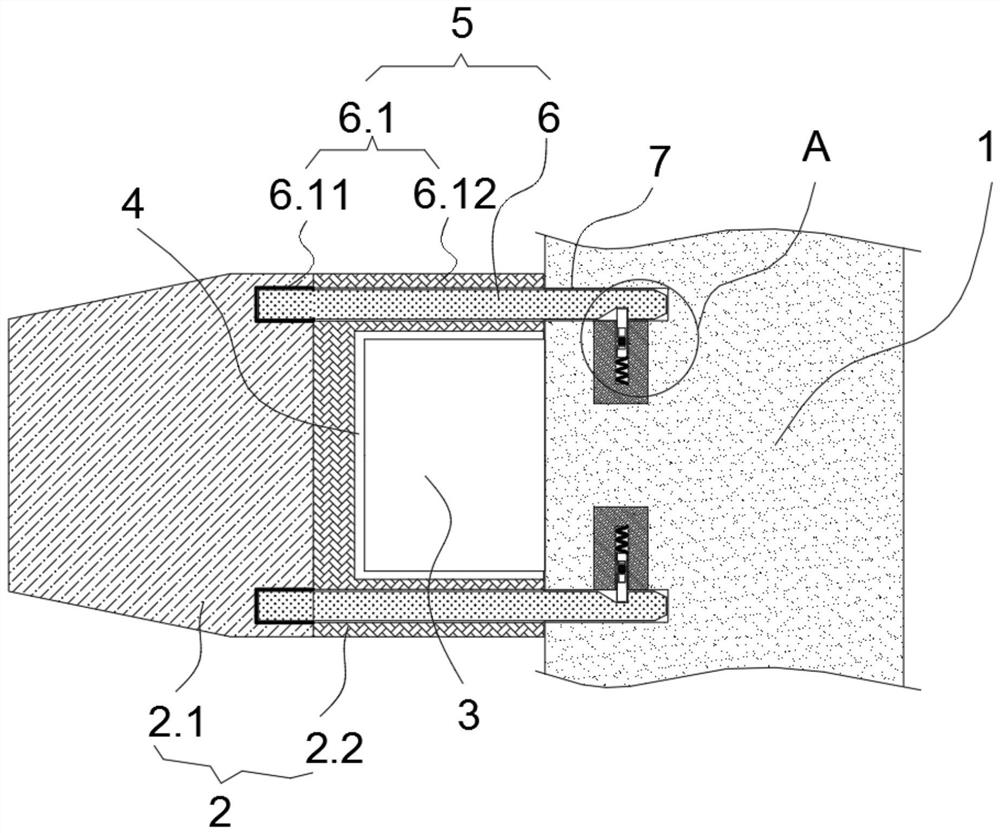
[0032] see Figure 1-8 , a cutter-suction marine reamer mechanism provided by an embodiment of the present invention includes a reamer blade 1 and a plurality of reamer teeth 2, a plurality of insertion columns 3 are arranged side by side on the reamer blade 1, and each reamer tooth 2 is inserted through The slots 4 are inserted one by one on each of the plug posts 3, and the reamer teeth 2 and the reamer blade 1 are also connected through a forced replacement mechanism 5, which includes:

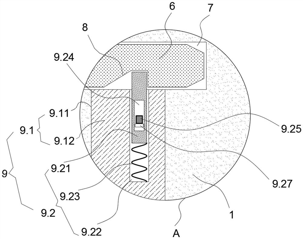
[0033] Connecting rod 6, one end of which is fixedly connected to the end wall of the blind hole 6.1 of the reamer tooth 2, and the other end is detachably connected to the reamer blade 1;

[0034] The connection between the hole end wall of the blind hole 6....


PUM


Abstract

The invention discloses a reamer mechanism for a cutter suction dredger, and relates to the technical field of excavating equipment. The reamer mechanism comprises a reamer blade and a plurality of reamer teeth, a plurality of inserting columns are arranged on the reamer blade side by side, and the reamer teeth are inserted into the inserting columns in a one-to-one correspondence mode through inserting grooves. The reamer teeth and the reamer blade are further connected through forced replacement mechanisms, each forced replacement mechanism comprises a connecting rod, one end of the connecting rod is fixedly connected to the hole end wall of the blind hole of the reamer teeth, and the other end of the connecting rod is detachably connected to the reamer blade. The fixed connection positions of the hole end walls of the blind holes and the connecting rods are located at the design abrasion limit positions of the reamer teeth. According to the reamer mechanism, the abrasion of the reamer teeth in use is gradually reduced and shortened, so that the connection effect of the forced replacement mechanisms on the reamer teeth is invalid, the reamer teeth are easily separated from the inserting columns, and related maintenance personnel are prompted to add new reamer teeth in time, so that a good digging effect is kept, and the working efficiency is improved.

Description

technical field [0001] The invention relates to the technical field of excavating equipment, in particular to a reamer mechanism for cutter suction ships. Background technique [0002] Cutter suction boat is a common water excavation equipment, through the high-speed rotating reamer mechanism to suck excavated crushed sediment into the hull, the reamer mechanism plays an indispensable and important role in the cutter suction boat. [0003] The existing patent announcement number is: CN204940394U, the name of the patent is "a cutter head for cutter suction dredger", the patent includes the bottom ring of the cutter, on which there are many arc-shaped cutter Knife arms, the tops of multiple reamer arms are fixed on the reamer hub, and there are multiple sets of matching reamer teeth on the reamer arms. The curvature of the reamer arms is divided into four types. The reamer arms contain the same The reamer teeth with adaptive curvature have the effects of small leakage, simple...

Claims


Application Information

Patent Timeline
Patent Type & Authority Applications(China)
IPC IPC(8): E02F3/88E02F3/92
CPCE02F3/88E02F3/885E02F3/9256E02F3/9268
Inventor 刘和明张春岭刘立超鲁磊杨嵩
Owner MINGGUANG CITY LIUXIANG PUMP IND
Why Eureka
Try Eureka