Method and apparatus for logging

a terminal and terminal technology, applied in data switching networks, power management, high-level techniques, etc., can solve the problems of increasing the total cost and time of radio network optimization and maintenance, unable to communicate with the base station currently, and difficult to achieve the effect of logging channel status or connection failure effectively

Active Publication Date: 2017-05-09
SAMSUNG ELECTRONICS CO LTD
View PDF22 Cites 0 Cited by
  • Summary
  • Abstract
  • Description
  • Claims
  • Application Information

AI Technical Summary

Benefits of technology

[0014]The apparatus and method of the present invention is advantageous in logging channel status or connection failure effectively.

Problems solved by technology

The conventional drive test is very time-consuming and laborious task performed in such a way that an operator carries the test apparatuses on a vehicle while performing the measurement task repeatedly for a long time.
Such a conventional drive test increases total costs and time of the radio network optimization and maintenance.
Otherwise, it is impossible to communicate with the base station currently, the terminal waits until it becomes possible to communicate with the base station.

Method used


Image

  • Method and apparatus for logging
  • Method and apparatus for logging
  • Method and apparatus for logging

Examples


first embodiment

[0073]FIG. 6 is a diagram illustrating an RRC connection establishment attempt procedure according to the present invention. A description is made of the PowerLimitationReached indicator and the numberOfPreamblesSen variable with reference to FIG. 6. The UE transmits the first preamble at step 600. The UE monitors whether a RAR message is received in response to the preamble during the RAR window. If it fails to receive RAR, the UE waits further for a backoff time. That is, the UE waits during the period 650 of sum of the RAR window and the backoff time.

[0074]Afterward, the UE transmits the second preamble at step 615. At this time, the UE increases the transmit power by power ramping step to transmit the preamble. The reason for increasing the transmit power is to increases the transmission success probability by increasing the UE transmission power in the case that the preamble transmission fails due to the bad radio channel status. The maximum number of preamble retransmissions i...

second embodiment

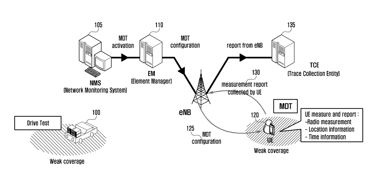
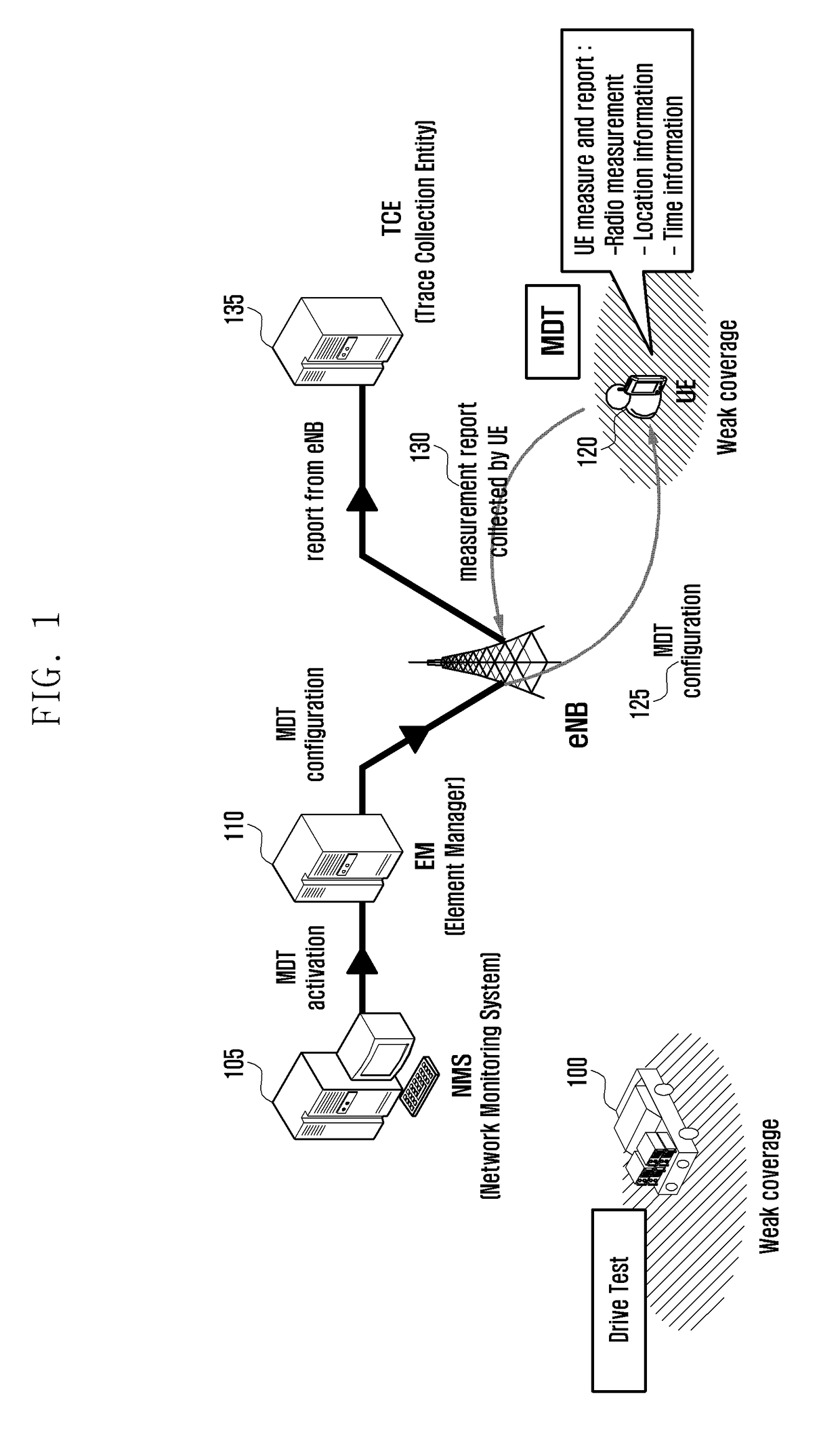
[0089]FIG. 9 is a diagram illustrating a GNSS location information acquisition procedure according to the present invention. The logged MDT is the procedure by which the UE logs the channel measurement information and location information and in the idle mode and, when transitioned to the connected mode, reports the logged information to the eNB.

[0090]At step 910, the eNB 905 notifies the eNB 900 whether it supports the positioning method capable of collecting accurate location information. Such positioning methods include standalone GNSS and network-assisted (NW-assisted) positioning.

[0091]The standalone GNSS is the method of deriving accurate location information of the corresponding UE using the signals received from a plurality satellites. Using the standalone GNSS, the UE is capable of acquiring the location information by itself without assistance of the eNB.

[0092]The NW-assisted positioning is the method of deriving the accurate location information of the corresponding UE in...


PUM


Abstract

The present invention relates to a method and an apparatus for logging a radio resource control (RRC) failure of user equipment (UE) and receiving the log. According to one embodiment of the present invention, a method for logging an RRC failure of UE may comprise the steps of: attempting random access; if the failure of random access is sensed, logging information on the failure; and if the success of random access is sensed, transmitting information on the failure logged before the success to a connected base station. According to one embodiment of the present invention, an apparatus and a method which effectively log a channel state or a connection failure can be provided.

Description

BACKGROUND OF THE INVENTION[0001]Field of the Invention:[0002]The present invention relates to a logging method and apparatus of a terminal in an mobile communication system and, in particular, to a method and apparatus for logging, when the terminal fails connection, the information on the connection failure and acquiring the location information of the terminal efficiently in idle mode.[0003]Description of the Related Art[0004]The mobile communication system developed for the user to communicate on the move. With the rapid advance of technologies, the mobile communication system has evolved to the level capable of providing high speed data communication service beyond the early voice-oriented services. Recently, as one of the next generation mobile communication system, Long Term Evolution-Advanced (LTE-A) is on the standardization by the 3rd Generation Partnership Project (3GPP). LTE is a technology for realizing high-speed packet-based communications with the data rate higher th...

Claims


Application Information

Patent Timeline
Patent Type & Authority Patents(United States)
IPC IPC(8): H04W24/10H04W24/00H04W74/08H04W76/02H04L12/26H04W4/02H04W4/029
CPCH04L43/0847H04W24/00H04W24/10H04W74/0833H04W76/027H04W76/18H04W4/02H04W74/08H04W28/00H04W4/029Y02D30/70H04W52/228
Inventor KIM, SANG BUMKIM, SOENG HUNJEONG, KYEONG IN
Owner SAMSUNG ELECTRONICS CO LTD
Why Eureka
Try Eureka