Connector

a technology of connecting rods and connectors, applied in the direction of fixed connections, coupling device connections, electric discharge lamps, etc., can solve the problems of contact buckles or deformations, difficult injection molding of housings, and thin wall thicknesses of housings, etc., to achieve easy manufacturing, stable connection, and simple construction

Inactive Publication Date: 2009-12-03
DDK LTD
View PDF8 Cites 0 Cited by
  • Summary
  • Abstract
  • Description
  • Claims
  • Application Information

AI Technical Summary

Benefits of technology

[0017]In view of the problems with the prior art described above, the invention has been completed, and it is an object of the invention to provide a connector which is easily manufactured because of its simple construction and achieves stable connection by ensuring sufficient displacements of contacts without any buckling and deformation of contacts, thereby precluding any defective or failed connection.
[0022](1) A connector 10 claimed in claim 1 is detachably fitted with a first connecting object and adapted to be connected to a second connecting object, including a plurality of contacts 14 each having a contact portion 22 adapted to contact said first connecting object, a fixed portion 24 to be fixed to a housing 12, and a connection portion 26 to be connected to said second connecting object; and the housing 12 having inserting holes 18 for arranging and holding said contacts 14 therein and a fitting opening 16 for receiving said first connecting object, wherein said housing 12 is provided on the side of said fitting opening 16 with recesses 20 which are continuous with said inserting holes 18, respectively, and opening into the fitting direction of the connector 10, and tips 28 of the contact portions 22 of said contacts 14 are positioned in said recesses 20, respectively, even in the state that said first connecting object has not been fitted in the connector 10, and wherein said recesses 20 are independent from one another corresponding to said respective contacts 14. Therefore, the connector according to the invention is easily manufactured because of its simple construction. Moreover, the connector according to the invention achieves stable connection by ensuring sufficient displacements of the contacts without any buckling and deformation of the contacts, thereby completely avoiding defective or failed connection.
[0023](2) The connector 10 as claimed in claim 2 is constructed in that said contacts 14 are each provided with a conducting portion 30 in the proximity of said contact portion 22, and that said housing is provided in each of recesses 20 with a relief portion 32 for said conducting portion 30 of the contact 14 and further provided with guides 38 on both sides in width directions of each of said recesses for guiding said first connecting object. Accordingly, the connector according to the invention is easily manufactured because of its simple construction and enables a mating connecting object to be easily conducted into the connector. Further, the connector according to the invention achieves stable connection by ensuring sufficient displacements of the contacts without any buckling and deformation of the contacts, thereby completely avoiding defective or failed connection.
[0024](3) The connector 10 as claimed in claim 1, constructed in that depth of said recesses 20 is 0.3 to 0.8 mm, while displacements of the contact portions 22 of said contacts 14 are 0.2 to 0.5 mm. Consequently, the connector according to the invention is easily manufactured because of its simple construction. Moreover, the connector according to the invention achieves stable connection by ensuring sufficient displacements of the contacts without any buckling and deformation of the contacts, thereby completely avoiding defective or failed connection.

Problems solved by technology

When the tips of the contacts protrude into the fitting opening, however, there would be a tendency for the contacts to be buckled or deformed upon inserting the first connecting object.
With the miniaturization of connector (extremely narrow pitches of conductors and miniaturization in width directions), wall thicknesses of the housing become thinner so that injection molding of the housing would become difficult.
Moreover, wobbling or tilting of contacts in directions of rows of the contacts could not be prevented, sometimes resulting in defective or failed connection.

Method used


Image

  • Connector
  • Connector
  • Connector

Examples


Embodiment Construction

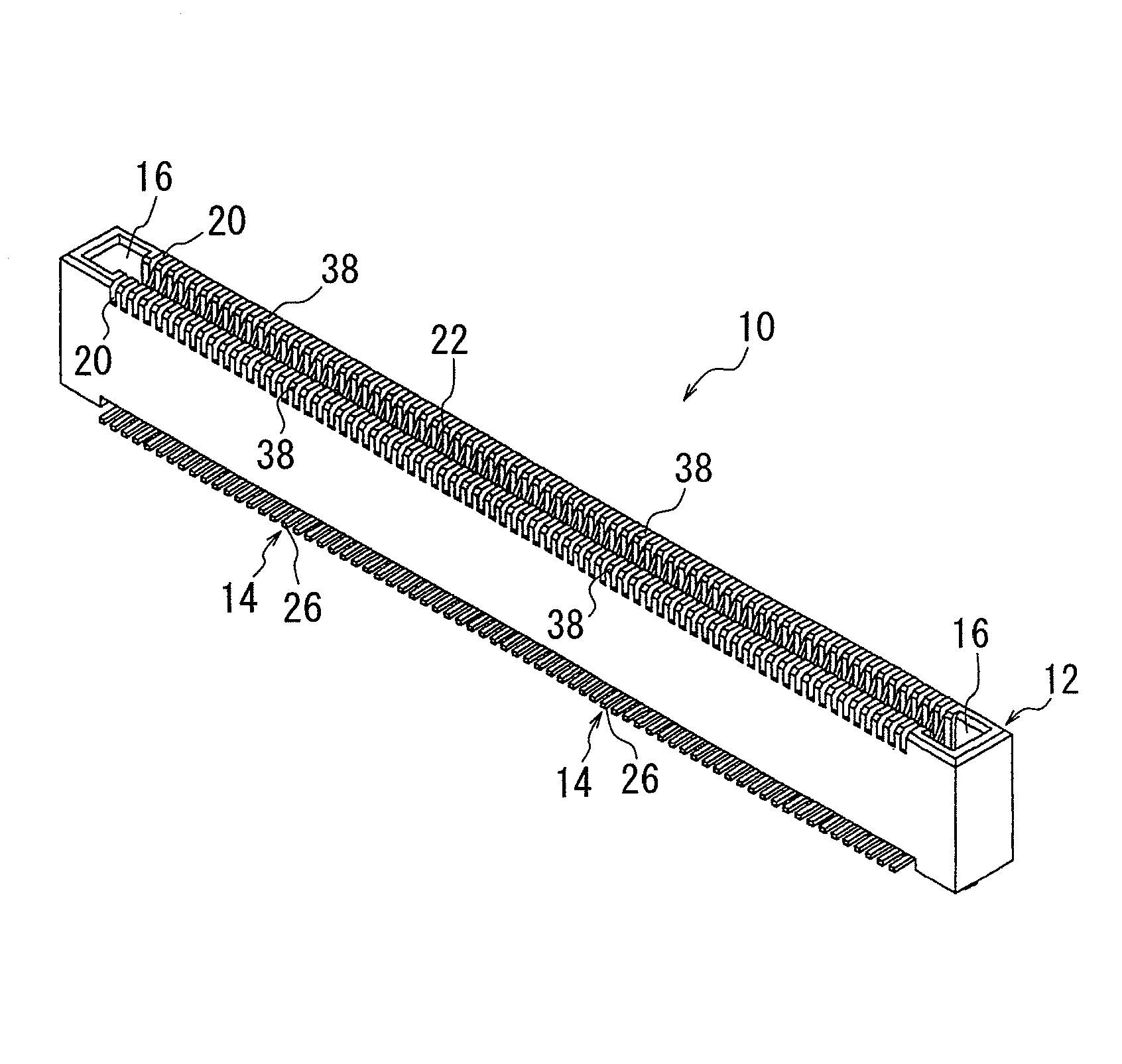
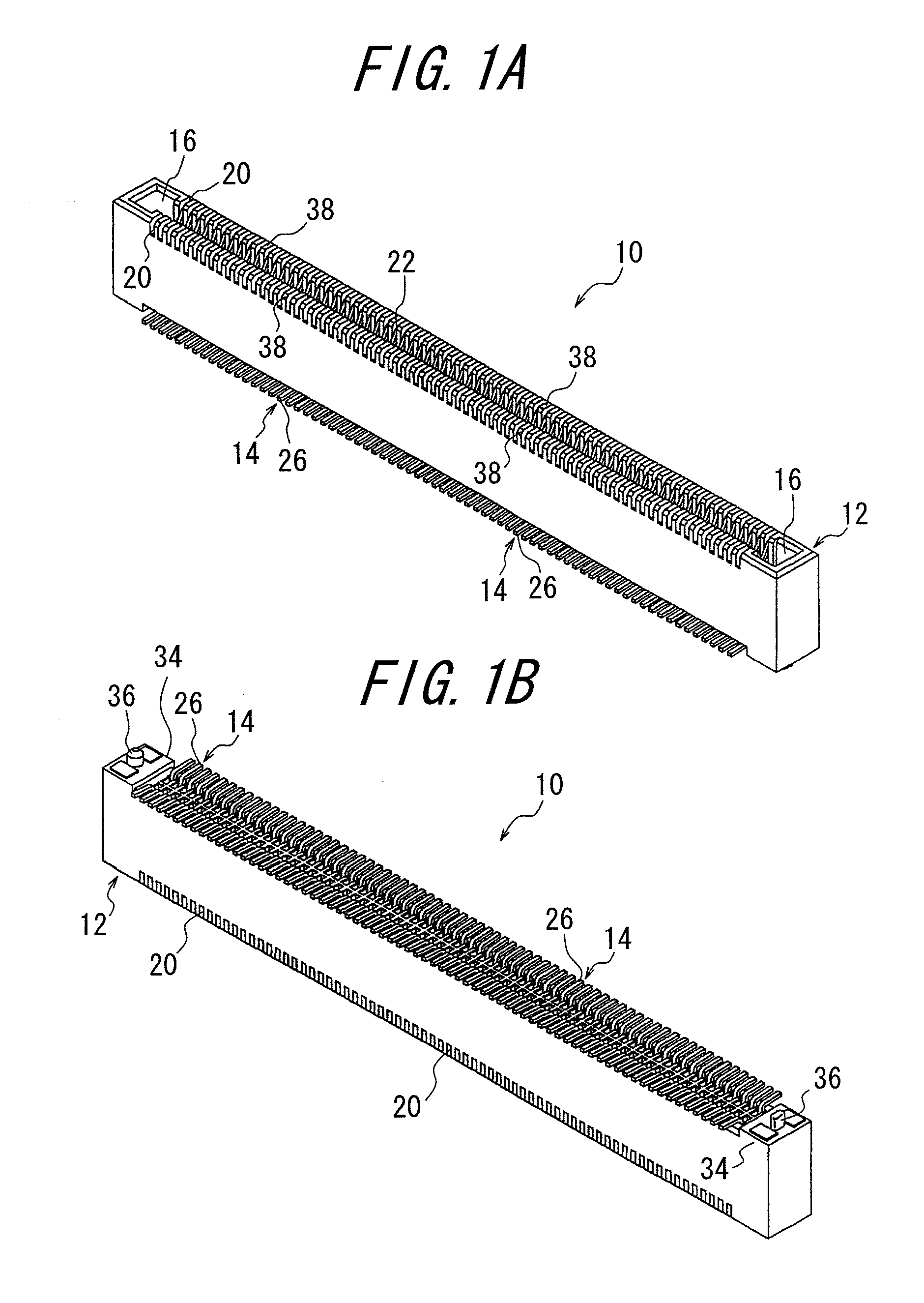
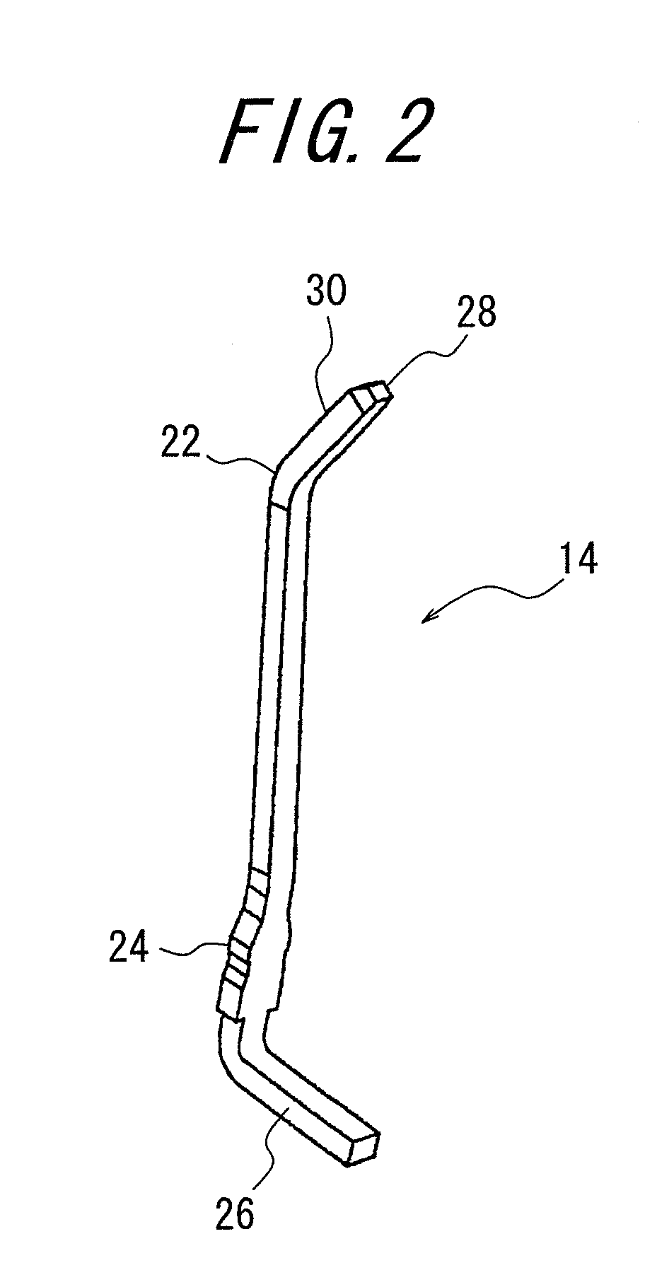
[0032]The subject feature of the invention lies in the connector 10 detachably fitted with a first connecting object and adapted to be connected to a second connecting object, including a plurality of contacts 14 each having a contact portion 22 adapted to contact said first connecting object, a fixed portion 24 to be fixed to a housing 12, and a connection portion 26 to be connected to said second connecting object; and the housing 12 having inserting holes 18 for arranging and holding said contacts 14 therein and a fitting opening 16 for receiving said first connecting object. Further, the housing 12 is provided on the side of said fitting opening 16 with recesses 20 which are continuous with said inserting holes 18 and opening into the fitting direction of the connector, and tips 28 of the contact portions 22 of said contacts 14 are positioned in said recesses 20 even in the state that said first connecting object has not been fitted in the connector 10, and further said recesses...


PUM


Abstract

A connector includes a plurality of contacts each having a contact portion adapted to contact a first connecting object, a fixed portion to be fixed to a housing, a connection portion to be connected to a second connecting object; and the housing having inserting holes for arranging and holding the contacts therein, and a fitting opening for receiving the first connecting object. The housing is provided on the side of the fitting opening with recesses which are continuous with the inserting holes, respectively, and opening into the fitting direction of the connector, and tips of the contact portions of the contacts are positioned in the recesses, respectively, even in the state that the first connecting object has not been fitted in the connector. The recesses are respectively independent from one another corresponding to the contacts. The connector thus constructed is simple in construction and easily manufactured and achieves a stable electrical connection by ensuring sufficient displacements of the contacts without buckling and deformation of the contacts, thereby preventing any defective or failed connection.

Description

BACKGROUND OF THE INVENTION[0001]This invention relates to a connector for use with electric and electronic appliances such as industrial machines, automobiles, personal computers, and the like, and more particularly to a connector capable of ensuring sufficient displacements of contact portions of contacts even if the width of the connector is limited to 2.5 to 3 mm, and obtaining stable electrical connection without any deformation of the contacts.[0002]Inherently, a connector is detachably fitted with a first connecting object, and is connected to a second connecting object. Therefore, the connector comprises at least a plurality of contacts each having a contact portion adapted to contact the first connecting object, a fixed portion to be fixed to a housing, and a connection portion to be connected to the second connecting object, and the housing having inserting holes for arranging and holding the contacts therein and a fitting opening for receiving the first connecting object....

Claims


Application Information

Patent Timeline
Patent Type & Authority Applications(United States)
IPC IPC(8): H01R27/02H01R12/71
CPCH01R12/57H01R12/721H01R13/422
Inventor FUKAZAWA, TAKEKIYOSHIMI, TAKANOBUHIDA, MASATO
Owner DDK LTD
Why Eureka
Try Eureka