Fan assembly and inverter

A fan assembly and inverter technology, applied to pump components, electrical components, non-variable pumps, etc., can solve the problems of increasing the vibration of the fan assembly, increasing the noise of the fan assembly, and increasing the aerodynamic noise, etc., to achieve improved Effects of transmission loss, efficient heat dissipation, and noise improvement

Pending Publication Date: 2021-09-07
SUNGROW POWER SUPPLY CO LTD
View PDF8 Cites 0 Cited by
  • Summary
  • Abstract
  • Description
  • Claims
  • Application Information

AI Technical Summary

Problems solved by technology

The disadvantage of this method is that after the speed of the fan main body increases, the vibration of this structure will intensify, which will easily excite the natural frequency of the parts in contact with it, forming resonance, and increasing the vibration generated by the rotation of the fan assembly; in addition, because the fan main body Installed close to the fan guard, when the main body of the fan rotates at high speed, the air flows through the fan guard to form a high-order vortex, which increases the aerodynamic noise and increases the noise generated when the fan assembly rotates

Method used


Image

  • Fan assembly and inverter
  • Fan assembly and inverter
  • Fan assembly and inverter

Examples


Embodiment 1

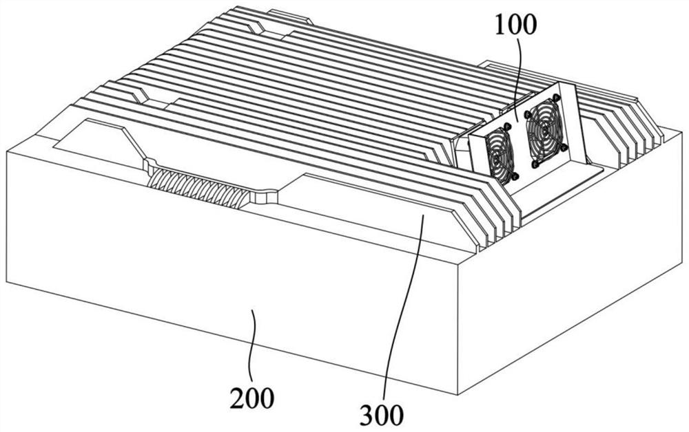
[0052] Such as figure 1 As shown, the present embodiment provides a fan assembly 100, the fan assembly 100 is mainly used to dissipate heat for an inverter, but is not limited thereto, and may also dissipate heat for other devices.

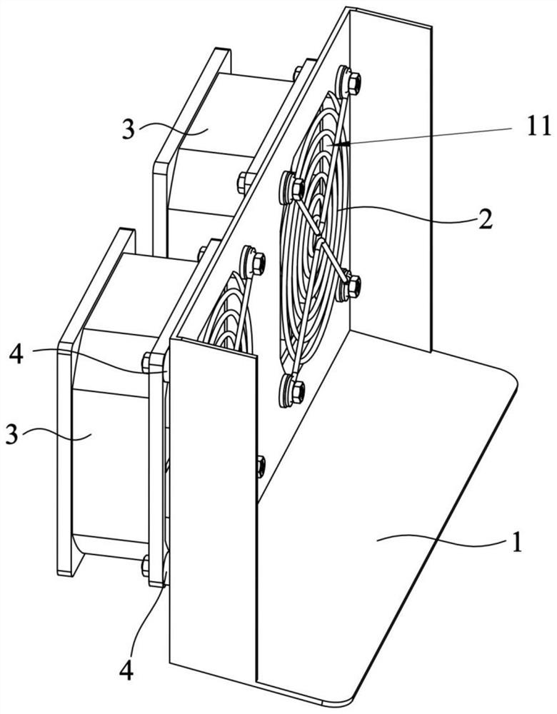
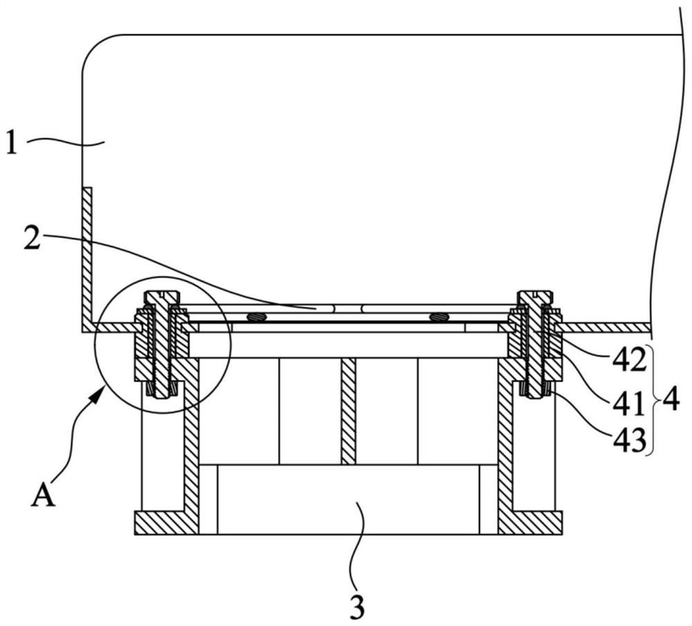
[0053] Specifically, as figure 2 As shown, the fan assembly 100 provided in this embodiment includes a fan bracket 1, a fan guard 2 and a fan main body 3, the fan bracket 1 is provided with an air inlet 11, the air inlet 11 is covered with the fan guard 2, and the fan main body 3 is installed On the fan bracket 1 and facing the air inlet 11, the fan guard 2 can ensure the air circulation at the air inlet 11, and also protect the fan main body 3 to prevent foreign matter from entering the fan main body 3 and causing danger. Avoid accidentally touching the fan body 3 to ensure personal safety. The main body of the fan 3 rotates so that the air passes through the fan guard 2 from the air inlet 11 to realize air circulation and realize the effect o...

Embodiment 2

[0082] The structure of the fan assembly 100 disclosed in this embodiment is basically the same as that of Embodiment 1. The difference between the fan assembly 100 disclosed in this embodiment and Embodiment 1 lies in that: the fan main body 3 and the noise reduction mounting part 4 are integrally formed.

[0083] Specifically, as Figure 7 As shown, the fan body 3 and the vibration-damping foot pad 411 are integrally formed, which improves the connection stability between the fan body 3 and the vibration-damping foot pad 411, and facilitates the installation of the fan body 3 on the fan bracket 1. Only the vibration-damping The clamping groove 4112 of the foot pad 411 is clamped into the third installation hole 12 and passes through.


PUM


Abstract

The invention relates to the technical field of inverter heat dissipation, in particular to a fan assembly and an inverter. The fan assembly comprises a fan mesh enclosure, a fan main body and a noise reduction mounting part, the fan main body is right opposite to an air inlet, the air inlet is covered with the fan mesh enclosure, and the noise reduction mounting part is arranged on the fan main body so that the spacing distance between the fan main body and the fan mesh enclosure can reach the preset distance. The noise reduction mounting part is configured to mount the fan main body on a to-be-mounted part in a buffering mode. The noise reduction mounting part can enable the spacing distance between the fan main body and the fan mesh enclosure to reach the preset distance, so that high-order vortex is prevented from being formed when air flows through the fan mesh enclosure, and aerodynamic noise is reduced. In addition, the noise reduction mounting part plays a role in vibration isolation between the fan main body and the to-be-mounted part, and the sound quality is improved. According to the provided inverter, by applying the fan assembly, resonance can be prevented from being formed between the fan main body and the to-be-mounted part, aerodynamic noise can be reduced, and the sound quality can be improved.

Description

technical field [0001] The invention relates to the technical field of inverter heat dissipation, in particular to a fan assembly and an inverter. Background technique [0002] Due to the increasing demand for inverter power and smaller size requirements in the market, the heat dissipation problem of the inverter is deteriorating, so the performance of the fan assembly is required to be continuously improved, and the air volume of the fan assembly needs to be increased. Therefore, the fan assembly The speed of the fan is getting higher and higher, but the increase of the wind speed will cause the fundamental frequency vibration of the fan assembly to increase, the noise will deteriorate, and the sound quality will decrease. [0003] At present, most of the installation methods of the existing fan assembly are to directly fix the fan main body on the component to be installed through screws, and at the same time install the fan guard on the fan main body. The disadvantage of...

Claims


Application Information

Patent Timeline
Patent Type & Authority Applications(China)
IPC IPC(8): F04D25/16F04D29/70F04D29/66F04D29/64H05K7/20
CPCF04D25/166F04D29/703F04D29/661F04D29/668F04D29/646H05K7/20136H05K7/20418F04D29/601F04D25/0613Y02B30/70F04D19/002H05K7/20909
Inventor 杨鑫周杰姚琦
Owner SUNGROW POWER SUPPLY CO LTD
Why Eureka
Try Eureka