Joining a laminated core to a shaft

A lamination and lamination group technology, applied in the direction of magnetic circuit shape/style/structure, electromechanical devices, magnetic circuit rotating parts, etc., can solve problems such as adhesive durability limitations

Pending Publication Date: 2021-09-07
SIEMENS AG
View PDF0 Cites 0 Cited by
  • Summary
  • Abstract
  • Description
  • Claims
  • Application Information

AI Technical Summary

Problems solved by technology

[0007] The hardening time must also be taken into account when gluing the joint, in addition, the durability of the...

Method used


Image

  • Joining a laminated core to a shaft
  • Joining a laminated core to a shaft
  • Joining a laminated core to a shaft

Examples


Embodiment Construction

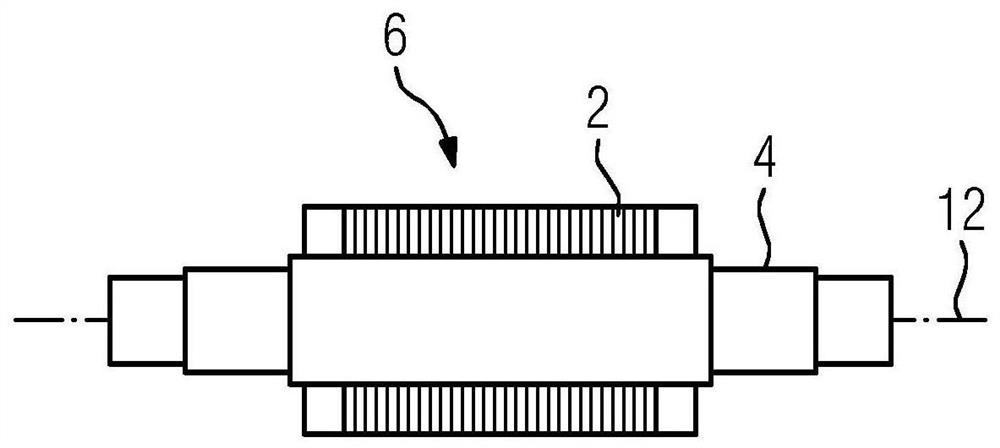
[0044] figure 1 In principle, a longitudinal section through a shaft 4 is shown, on which the laminated core 2 of the rotor 6 is positioned. This shows the end state that the builder of the motor strives to achieve between the lamination pack 2 and the shaft, in order to transfer the torque of the motor 24 to the shaft 4 via the rotor 6, or vice versa in the case of a generator lead into the motor.

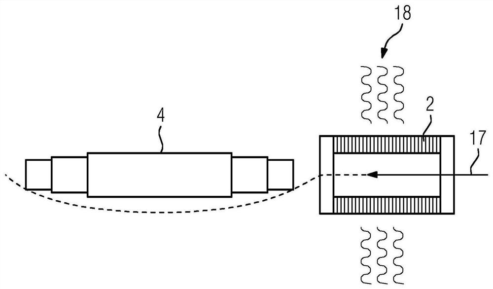
[0045] figure 2 A production method according to the prior art is schematically shown, in which the laminated core 2 is pressed axially onto the shaft 4 by an axial joining force 17 with additional heating 18 of the laminated core 2 . In this case, there is always the risk of buckling of the shaft 4 (indicated by dashed lines) in the event of an excessively high axial joining force 17 . In this case, however, joining force 17 ultimately determines the torsion resistance and torque transmission properties of laminated core 2 and shaft 4 .

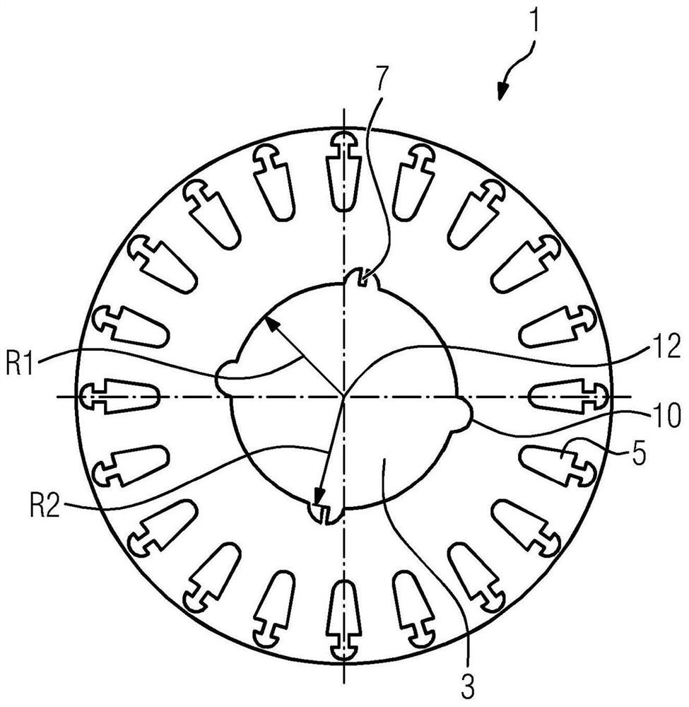
[0046] image 3 The present laminat...


PUM


Abstract

The invention relates to a lamination (1) of a rotor (6) of a rotary dynamo-electric machine having a shaft bore (3) with a radius (R1), at least two pull-through grooves (7), and two intermediate space recesses (10), wherein each of the threading grooves (7) has at least one lamination tongue (8) facing radially inwards towards the axis (12) such that the lamination tongue (8) ends (9) facing radially inwards lie on a radius (R2), R2 being less than R1.

Description

technical field [0001] The invention relates to a laminated core for a rotor of a rotating electrical machine, a laminated core for a rotor of a rotating electrical machine, an electrical machine with such a configured rotor, and a method for producing the rotor. Background technique [0002] Electric machines are used as generators or engines. In the case of an engine, the torque generated by it is transmitted from the rotor or rotor lamination pack to the shaft. Here, the stability of the lamination stack on the shaft must be ensured. This applies primarily in the case of vertically configured engines. The press fit required for this therefore has a relatively high interference of the shaft with respect to the stack bore or the shaft bore of the laminated core. [0003] When pressing the laminated core, the shaft is ideally supported on the shaft mirror in order to obtain the largest possible surface area as support. In order to limit the axial pressing or joining forc...

Claims


Application Information

Patent Timeline
IPC IPC(8): H02K1/28H02K15/02
CPCH02K1/28H02K15/028H02K7/003
Inventor 克劳斯·比特纳克劳斯·基希纳马蒂亚斯·瓦尔穆特
Owner SIEMENS AG
Why Eureka
Try Eureka