Clamping rib forming mechanism of motor output shaft

A molding mechanism and output shaft technology, applied in the manufacture of motor generators, electrical components, electromechanical devices, etc., can solve the problems that the clamping molding device 50 cannot maintain synchronization consistency for a long time, poor molding effect, positioning error, etc.

Active Publication Date: 2021-09-10
TANAC AUTOMATION
View PDF6 Cites 0 Cited by
  • Summary
  • Abstract
  • Description
  • Claims
  • Application Information

AI Technical Summary

Problems solved by technology

In traditional motors, the rotating shaft in the motor is usually externally formed to form snap ribs, and then the formed rotating shaft is installed into the motor. This installation method is complicated, the motor shell is damaged by force, and the rotating shaft is easily deformed.
[0003]In the existing motor installation, the motor is installed first, and then the motor is fixed and limited, and the ribs are formed for the shaft part, so as to realize the motor installation, but the motor The overall volume is large, and the corresponding positioning limit is difficult. The existing positioning mechanisms are all rigid positioning, and the positioning has errors, which makes the motor slightly offset, resulting in poor forming effect of the clamping ribs.
In the forming process, there are generally multiple clamping and forming devices 50 distributed around the circumference, each clamping and forming device 50 will bear the opposite clamping force, the failure rate of the device is high, and each clamping and forming device 50 cannot be maintained for a long time Synchronous consistency, periodic debugging and replacement are required, and the molding effect is not good

Method used


Image

  • Clamping rib forming mechanism of motor output shaft
  • Clamping rib forming mechanism of motor output shaft
  • Clamping rib forming mechanism of motor output shaft

Examples


Embodiment Construction

[0025] The specific embodiments of the present invention will be described in further detail below. It should be understood that the descriptions of the embodiments of the present invention herein are not intended to limit the protection scope of the present invention.

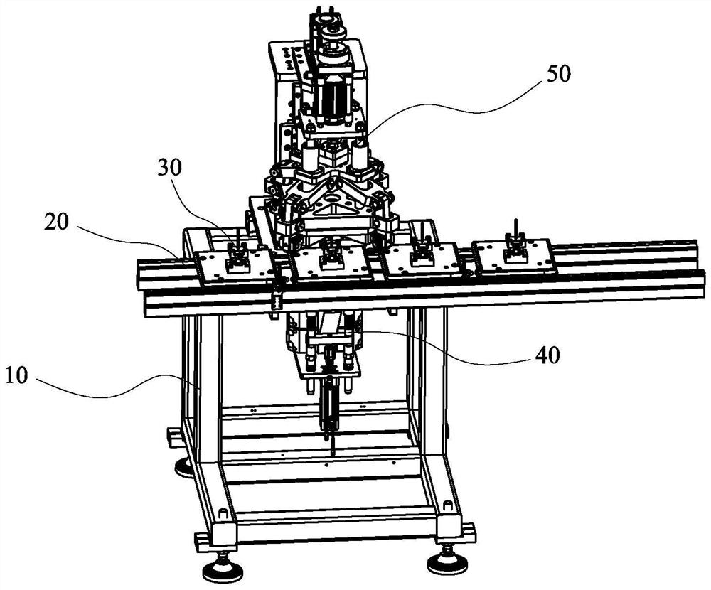
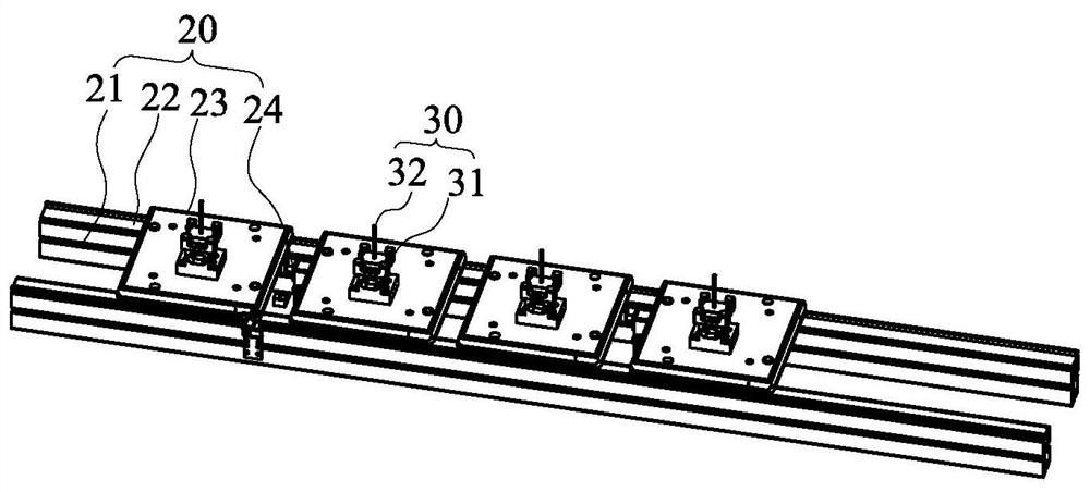
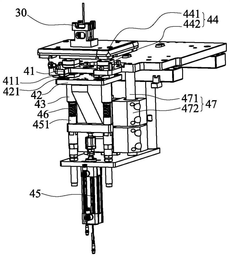
[0026] see Figure 1 to Figure 4 , which is a schematic structural diagram of a clamping rib forming mechanism for a motor output shaft provided by the present invention. A clamping rib forming mechanism for a motor output shaft includes a support frame 10, a conveying device 20 disposed on the support frame 10, a motor limiting device 30 disposed on the conveying device 20, and a conveying device 30 disposed on the conveying device 20. A flexible positioning device 40 on the support frame 10 and located below the motor limiting device 30 , and a forming device 50 arranged on the support frame 10 . It is conceivable that the clamping rib forming mechanism of the motor output shaft also includes other functio...


PUM


Abstract

The invention discloses a clamping rib forming mechanism of a motor output shaft. The mechanism comprises a supporting frame, a conveying device arranged on the supporting frame, a motor limiting device arranged on the conveying device, a flexible positioning device arranged on the supporting frame and located below the motor limiting device, and a forming device mounted on the supporting frame. The forming device comprises a mounting frame, a downward pressing driving structure arranged on the mounting frame, at least two synchronous steering clamping structures arranged on the mounting frame and connected with the downward pressing driving structure, and at least two forming driving parts correspondingly embedded in the synchronous steering clamping structures. According to the clamping rib forming mechanism of the motor output shaft, the failure rate of multiple driving sources is reduced through single-driving-source output of the downward pressing driving structure, damage and instability caused by an original opposite-direction stress clamping manner are avoided, the clamping stability is further improved, and the reliability of a clamping structure is enhanced.

Description

technical field [0001] The invention belongs to the technical field of forming equipment, in particular to a clamping rib forming mechanism for an output shaft of a motor. Background technique [0002] Motor, commonly known as "motor", refers to an electromagnetic device that realizes the conversion or transfer of electrical energy according to the law of electromagnetic induction. In traditional motors, the shaft in which the motor is installed is generally externally formed to form clamping ribs, and the formed shaft is installed into the motor. This installation method is complicated, the motor housing is greatly damaged by force, and the shaft is easily deformed. [0003] The existing motor installation is to install first, and then fix the motor as a whole to the limit, and form the clamping rib for the rotating shaft part, so as to realize the motor installation, but the overall volume of the motor is large, and the corresponding positioning limit is difficult. Some p...

Claims


Application Information

Patent Timeline
Patent Type & Authority Applications(China)
IPC IPC(8): B21C23/00B21C23/21H02K15/00H02K15/14
CPCB21C23/00B21C23/21H02K15/00H02K15/14
Inventor 刘世成刘永松顾力伟许钧泓
Owner TANAC AUTOMATION
Why Eureka
Try Eureka