Cutting tool convenient to replace and used for machining of numerical control machine tool

A technology that is convenient for replacement and CNC machine tools, applied in the field of CNC machine tools, can solve the problems of low efficiency of milling cutter replacement and complicated installation and operation.

Active Publication Date: 2021-09-10
HANGZHOU VOCATIONAL & TECHN COLLEGE
View PDF7 Cites 0 Cited by
  • Summary
  • Abstract
  • Description
  • Claims
  • Application Information

AI Technical Summary

Problems solved by technology

[0004] The present invention proposes a cutting tool that can be easily replaced for CNC machine tool processing, which solves the problem of complex in

Method used


Image

  • Cutting tool convenient to replace and used for machining of numerical control machine tool
  • Cutting tool convenient to replace and used for machining of numerical control machine tool
  • Cutting tool convenient to replace and used for machining of numerical control machine tool

Examples


Embodiment 1

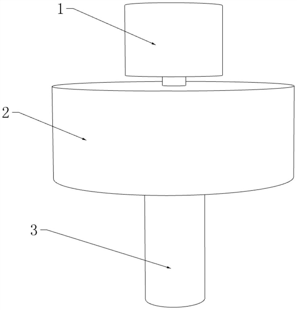
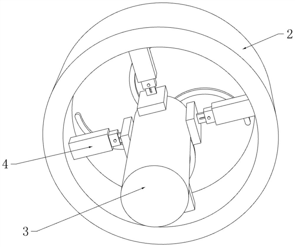
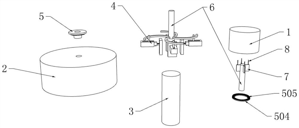
[0035] refer to figure 1 , figure 2 and Figure 8 , a cutting tool that is conveniently replaced for CNC machine tool processing, including an adjusting cap 1, a mounting part 2 and a milling cutter mounting head 3, the adjusting cap 1 and the mounting part 2 are both arranged in a hollow structure, and the bottom end is provided with an opening for milling The knife installation head 3 is installed inside the installation part 2 .

[0036] refer to image 3 and Figure 8 , the inside of the adjustment cap 1 is provided with a mounting groove 102, and the inside of the adjustment cap 1 is provided with a limit groove 101 distributed in an annular array around the installation groove 102, and the drive rod 6 is slidably installed inside the installation groove 102, and the drive rod 6 The rod body of the rod body is fixedly connected with a limiting plate 7 in a circular array and corresponding to the limiting groove 101. The end of the driving rod 6 extends to the inside ...

Embodiment 2

[0042] refer to Figure 6 , Figure 7 and Figure 9-11 One end of the third mounting plate 405 is slidably installed inside the second mounting plate 404, the top inner wall of the second mounting plate 404 is provided with a movable groove 4012, and the movable plate 408 is slidably installed inside the movable groove 4012, and the movable groove 4012 The first return spring 409 distributed in a rectangular array is fixedly connected between the top inner wall and the top of the movable plate 408, and the bottom end of the movable plate 408 is fixedly connected with a push rod 407, and the push rod 407 slides through the third mounting plate 405 and the first mounting plate 405. The bottom side walls of the second mounting plate 404 extend to the bottom of the second mounting plate 404 and are fixedly connected with an anti-off block. The bottom of the movable plate 408 is equipped with two groups of first positioning teeth 4010 that are symmetrically distributed. Two sets ...


PUM


Abstract

The invention discloses a cutting tool convenient to replace and used for machining of a numerical control machine tool, relates to the field of numerical control machine tools, and aims at solving the problem that the replacement efficiency is low when a milling cutter is damaged due to the fact that an existing cutting tool of the numerical control machine tool is complex to install and operate. Now the following scheme is provided, specifically, the cutting tool comprises an adjusting cap, amounting part and a milling cutter mounting head; the adjusting cap and the mounting part are of hollow structures, openings are formed in the bottom ends of the adjusting cap and the mounting part, the milling cutter mounting head is mounted in the mounting part, a clamping mechanism matched with the milling cutter mounting head is arranged in the mounting part, a positioning mechanism is arranged between the adjusting cap and the mounting part, a mounting groove is formed in the adjusting cap, and limiting grooves distributed in an annular array are formed in the adjusting cap around the mounting groove. Compared with traditional milling cutter dismounting and mounting, operation is more convenient, the milling cutter dismounting and mounting efficiency can be effectively improved, the device can be suitable for milling cutter mounting heads of different shapes, and the effective use range of the device is widened.

Description

technical field [0001] The invention relates to the field of numerical control machine tools, in particular to a cutting tool which can be easily replaced for the machining of numerical control machine tools. Background technique [0002] CNC machine tool is the abbreviation of numerical control machine tool, which is an automatic machine tool equipped with a program control system. The control system can logically process programs with control codes or other symbolic instructions, decode them, express them in coded numbers, and input them into the numerical control device through the information carrier. After calculation and processing, various control signals are sent by the numerical control device to control the movement of the machine tool, and the parts are automatically processed according to the shape and size required by the drawing. CNC machine tools solve complex, precise, small-batch, and multi-variety parts processing problems. It is a flexible, high-efficienc...

Claims


Application Information

Patent Timeline
IPC IPC(8): B23C5/26B23C9/00
CPCB23C5/26B23C9/005
Inventor 丁媛媛吕哲翀杨斌金俊金寅德
Owner HANGZHOU VOCATIONAL & TECHN COLLEGE
Why Eureka
Try Eureka