Eureka AIR delivers breakthrough ideas for toughest innovation challenges, trusted by R&D personnel around the world.

Automatic press-fitting system and assembling method for ball screw pair supporting sleeves

A ball screw pair, support sleeve technology, applied in metal processing, metal processing equipment, manufacturing tools, etc., can solve the problems of inability to apply support sleeve mass production, small support sleeve installation, poor consistency of installation accuracy, etc.

Active Publication Date: 2021-09-10
BEIJING MECHANICAL EQUIP INST
View PDF9 Cites 3 Cited by
  • Summary
  • Abstract
  • Description
  • Claims
  • Application Information

AI Technical Summary

Problems solved by technology

[0005] In view of the above analysis, the present invention aims to provide an automatic press-fitting system and assembly method for the supporting sleeve of the ball screw pair, which is used to solve the problem that the supporting sleeve is affected by the hammer impact when the supporting sleeve is knocked and installed by the manual pressing method. It is prone to appearance damage, and due to the relatively small force bearing area, the support sleeve is prone to problems such as improper installation, poor installation accuracy consistency, and cannot be applied to mass production of support sleeve press fitting

Method used


Image

  • Automatic press-fitting system and assembling method for ball screw pair supporting sleeves
  • Automatic press-fitting system and assembling method for ball screw pair supporting sleeves
  • Automatic press-fitting system and assembling method for ball screw pair supporting sleeves

Examples


Embodiment 1

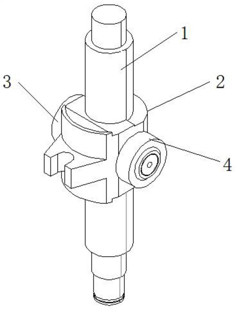
[0055] Such as figure 1 As shown, the ball screw pair includes a screw 1 and a nut 2, and the two sides of the nut 2 are sleeved with a first support sleeve 3 and a second support sleeve 4 by way of interference fit. The automatic press-fitting system of the supporting sleeve of the ball screw pair of the present invention is used to realize the installation of the first supporting sleeve 3 and the second supporting sleeve 4 on the mounting columns on both sides of the nut 2 respectively.

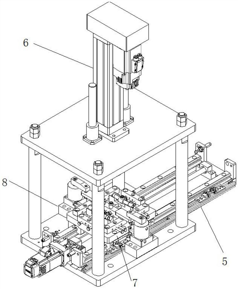
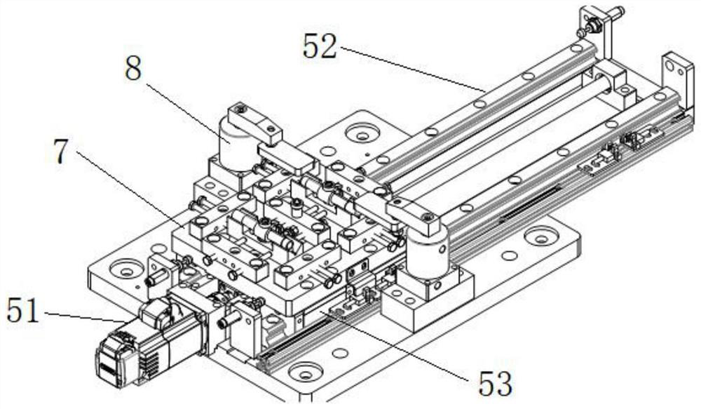
[0056] A specific embodiment of the present invention discloses an automatic press-fitting system for a ball screw auxiliary support sleeve, comprising: a slide rail mechanism 5, a press-fitting mechanism 6, a sliding fixture 7, an auxiliary positioning mechanism 8 and a turning mechanism. Wherein, the sliding fixture 7 is used for loading and positioning the ball screw pair, the sliding fixture 7 is arranged on the slide rail mechanism 5, and can be driven to slide through the slide rail m...

Embodiment 2

[0101] Another specific embodiment of the present invention improves the automatic press-fitting system of the ball screw auxiliary support sleeve in Embodiment 1, and provides a turning mechanism that is different from the servo turning mechanism 9. Specifically, the turning mechanism of this embodiment is Rotary flip mechanism.

[0102] Further, as Figure 11 , 12 As shown, the rotation turning mechanism includes: a support frame 901 , a rotation bracket 902 , a first rotation motor 903 , a second rotation motor 905 , a jaw bracket 906 and a jaw 907 . Specifically, the support frame 901 is erected above the linear guide rail 52 . A first rotating motor 903 is fixedly installed above the supporting frame 901 , the rotating frame 902 is rotatably installed on the supporting frame 901 , and the rotating frame 902 can rotate relative to the supporting frame 901 driven by the first rotating motor 903 . Specifically, one end of the rotating bracket 902 is provided with a rotati...

Embodiment 3

[0109] A specific embodiment of the present invention provides an automatic press-fit assembly method for the supporting sleeve of the ball screw pair. The automatic press-fitting system for the supporting sleeve of the ball screw pair in Embodiment 1 or 2 is used to carry out the second mounting on both sides of the ball screw pair. The press-fitting of a support sleeve 3 and the second support sleeve 4 comprises the following steps:

[0110]Step S1: When the sliding fixture 7 is in the first working position, place the first support sleeve 3 on the support sleeve positioning pin 75 on the sliding fixture 7; place the ball screw pair on the first screw pair on the sliding fixture 7 on the positioning block;

[0111] Step S2: Move the sliding fixture 7 to the second working position, the retractable press head 66 is axially aligned with the positioning pin 75 of the support sleeve, and the press-fit mechanism 6 picks up the first support sleeve 3; specifically, the press-fit m...


PUM


Abstract

The invention relates to an automatic press-fitting system and assembling method for ball screw pair supporting sleeves, belongs to the technical field of automatic assembly, and solves the problems of low assembly precision and complex operation of a mode of assembling the supporting sleeves by manual press-fitting, hot-fitting or cold-fitting in the prior art. The automatic press-fitting system comprises a sliding rail mechanism, a press fitting mechanism, a sliding clamp, an auxiliary positioning mechanism and a turnover mechanism, wherein the sliding clamp is used for loading the positioning support sleeves and ball screw pairs; the sliding clamp can slide on the sliding rail mechanism; the press-fitting mechanism is provided with a telescopic pressing head, and the supporting sleeves can be clamped into supporting sleeve clamping grooves of the telescopic pressing head and fixed through the auxiliary positioning mechanism; the supporting sleeves comprise a first supporting sleeve and a second supporting sleeve; the press-fitting mechanism can press-fit the first supporting sleeve on ball screw pairs by pressing the telescopic pressing head; the turnover mechanism can turn over the ball screw pairs, and the second supporting sleeve is pressed after the ball screw pairs are turned over. Automatic pressing of the ball screw pair supporting sleeves is achieved.

Description

technical field [0001] The invention relates to the technical field of automatic assembly, in particular to an automatic press-fitting system and an assembling method for a ball screw auxiliary support sleeve. Background technique [0002] As one of the transmission components of the mechanical structure, the supporting sleeve of the ball screw is widely used in various fields such as transportation, aerospace, and military products. The supporting sleeve of the ball screw pair is composed of a screw, a supporting sleeve and a nut, such as figure 1 shown. At present, the method of installing the support sleeve on both sides of the nut is manual press-fitting. The ball screw pair (composed of the screw and the nut) is fixed by simple tooling, and the support sleeve and the mounting columns on both sides of the nut are axially aligned. The installation of the support sleeve and the nut mounting column is realized by manual knocking. The main problems are that the support sle...

Claims


Application Information

Patent Timeline
IPC IPC(8): B23P19/02
CPCB23P19/02B23P19/001
Inventor 门广强程建安马俊王凯任宏刘杰
Owner BEIJING MECHANICAL EQUIP INST
Why Eureka
Eureka Blog
Learn More