
Sectional material feeding mechanism based on building material machinery and using method of sectional material feeding mechanism

A technology for feeding mechanism and profiles, applied in metal processing machinery parts, metal processing equipment, feeding devices, etc., can solve the problems of wasting labor, inconvenient use, and profile angle errors, etc.

Inactive Publication Date: 2021-09-10
朱敏杰
View PDF1 Cites 0 Cited by
  • Summary
  • Abstract
  • Description
  • Claims
  • Application Information

AI Technical Summary

Problems solved by technology

[0005] In order to solve the above-mentioned technical problems, the present invention provides a profile feeding mechanism based on building materials machinery and its use method, so as to solve the problem that when the existing profile supply mechanism is in use, cutting profiles at different angles needs to be manually adjusted. It is easy to cause a large error in the angle of the profile, which is inconvenient to use, and when the profile is processed and transported, it is necessary for others to open the fixture in advance before moving the profile, which is a waste of labor.

Method used


Image

  • Sectional material feeding mechanism based on building material machinery and using method of sectional material feeding mechanism
  • Sectional material feeding mechanism based on building material machinery and using method of sectional material feeding mechanism
  • Sectional material feeding mechanism based on building material machinery and using method of sectional material feeding mechanism

Examples


Embodiment

[0039] as attached figure 1 to attach Figure 8 Shown:

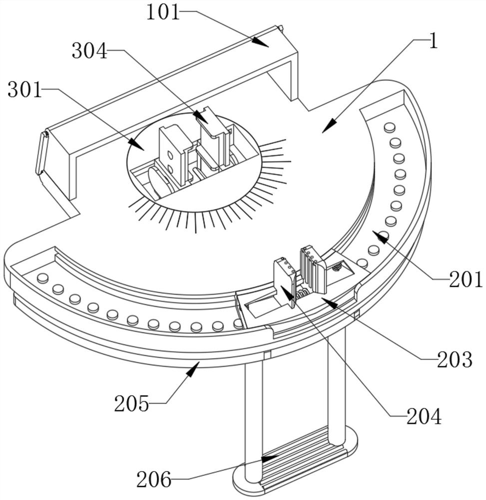
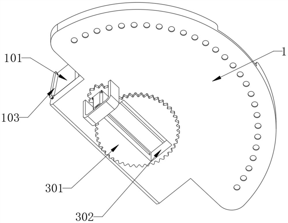
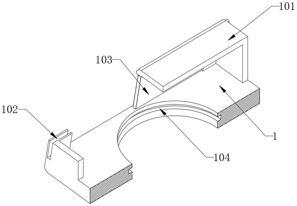
[0040] The invention provides a profile feeding mechanism based on building materials machinery and its use method, comprising: a main body 1, the side of the main body 1 is an arc-shaped structure, and the bottom of the main body 1 is equipped with a motor through a bracket, and a gear is installed on the top of the motor , and the side of the main body 1 is equipped with a fixing part 2; the fixing part 2, the chute 201 in the fixing part 2 is arranged on the top side of the main body 1, and the bottom plate 205 in the fixing part 2 is installed on the bottom side of the main body 1 by a spring; The guide 3, the guide 3 is installed inside the top groove 104, and the outside of the bottom of the carrier 301 in the guide 3 is provided with a sawtooth structure, the sawtooth structure at the bottom of the carrier 301 is in phase with the gear on the top of the motor at the bottom of the main body 1 engaged, and the car...


PUM


Abstract

The invention provides a sectional material feeding mechanism based on building material machinery and a using method of the sectional material feeding mechanism, and relates to the technical field of building material machinery. The sectional material feeding mechanism based on the building material machinery and the using method of the sectional material feeding mechanism aim to solve the problem that when an existing sectional material feeding mechanism is used, sectional material angle cutting is manually adjusted, and large errors are easily caused. The sectional material feeding mechanism comprises a main body, a fixing piece and a guiding piece; the side face of the main body is of an arc-shaped structure, a motor is arranged at the bottom of the main body through a support, and a fixing piece is arranged on the side face of the main body; a sliding groove in the fixing piece is formed in the side face of the top of the main body, and a bottom plate in the fixing piece is arranged on the side face of the bottom of the main body through a spring; and the guiding piece is arranged inside a top groove, a sawtooth-shaped structure is arranged on the outer side of the bottom of a carrier plate in the guiding piece, the sawtooth-shaped structure at the bottom of the carrier plate is meshed with a gear at the top end of the motor at the bottom of the main body, and the carrier plate is rotationally arranged inside the top groove. The motor at the bottom of the main body drives the carrier plate to rotate, so that a sectional material is aligned with scales outside the top of the top groove to improve the sectional material cutting precision.

Description

technical field [0001] The invention belongs to the technical field of building material machinery, and more specifically relates to a profile feeding mechanism based on building material machinery and a usage method thereof. Background technique [0002] Building materials machinery refers to various production and mixing machinery used in the production of cement, cement products, glass, aluminum ingots, metal materials and other building materials. The profiles are iron or steel and materials with certain strength and toughness are rolled and extruded Objects with a certain geometric shape made by casting, casting and other processes. The profiles can be used alone or further processed into other manufactured products. They are often used in building structures and manufacturing installations. [0003] For example, the application number: CN201810937345.8 relates to a profile feeding and clamping mechanism, including a base, a rectangular groove is opened on the base, and...

Claims


Application Information

Patent Timeline
IPC IPC(8): B23Q5/22
CPCB23Q5/22
Inventor 朱敏杰
Owner 朱敏杰
Learn More