Supporting device for underground comprehensive pipe gallery and using method thereof
A technology of integrated pipe gallery and supporting parts, which is applied to cable installation in underground pipelines, cable installation, underwater structures, etc. And other issues
- Summary
- Abstract
- Description
- Claims
- Application Information
AI Technical Summary
Problems solved by technology
Method used
Image
Examples
Embodiment 1
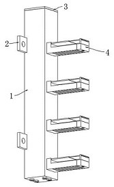
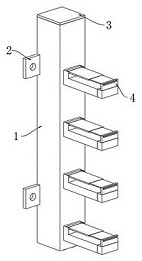
[0043] Please refer to Figure 1-6 As shown, a supporting device for an underground comprehensive pipe gallery includes a fixed column 1, and also includes: an insertion hole 101 opened on one side of the fixed column 1, and a positioning hole 102 is opened on the top of the fixed column 1, and the positioning hole 102 It communicates with the socket 101, and a positioning assembly 3 is fixedly installed in the positioning hole 102. The positioning assembly 3 includes a top plate 301. A positioning rod 302 is installed on the bottom of the top plate 301. The end of the positioning rod 302 away from the top plate 301 is provided with threads, and the positioning The threaded end of the rod 302 is threadedly connected with a positioning nut 303, and both sides of the fixed column 1 are equipped with a fixed block 2, and a bolt hole is provided in the fixed block 2, and the supporting bracket 4 installed on one side of the fixed column 1, the supporting bracket 4. It includes a s...
Embodiment 2
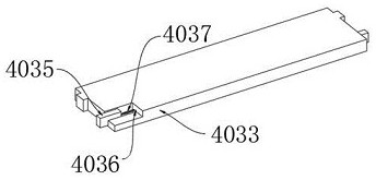
[0045] On the basis of Example 1, please refer to Figure 1-10 As shown, the supporting member 401 includes a supporting base 4011, one end of the supporting base 4011 is provided with a movable groove 4014, and the bottom of the supporting base 4011 is provided with a limiting groove 4015, and the limiting groove 4015 communicates with the movable groove 4014. The opposite top of the supporting base 4011 is provided with a rotating groove 4012, and a shaft 4013 is fixedly installed in the rotating groove 4012. The top of the supporting base 4011 is provided with a mounting groove. Plate 4028, a plate groove 4029 is opened in the positioning plate 4028, a lift groove 4022 is opened at the bottom of the extension plate 4021, a lift plate 4023 is installed in the lift groove 4022, a bar 4024 is installed at the bottom of the lift plate 4023, and the bottom of the extension plate 4021 There is a groove 4025, and an adjustment shaft 4026 is installed in the groove 4025. The smooth...
Embodiment 3
[0047] On the basis of Example 2, please refer to Figure 1-10 As shown, the present invention also provides a method for using a supporting device for an underground comprehensive utility gallery, comprising the following steps:
[0048] Step 1: Insert the supporting base 4011 into the socket 101 , insert the positioning rod 302 into the positioning hole 102 and the installation groove, and screw on the positioning nut 303 .
[0049] Step 2, turn the hand wheel 4027, the hand wheel 4027 drives the adjustment shaft 4026 to rotate, so that the lifting plate 4023 moves upward in the lifting groove 4022, and the bar 4024 is moved out of the limiting groove 4015.
[0050] Step 3. Pull the extension piece 402 according to the length of the supporting bracket 4 to be used. When the length of the supporting bracket 4 meets the usage requirements, reversely turn the hand wheel 4027 to insert the bar 4024 into the limiting groove 4015, so that The supporting piece 401 and the extensio...
PUM
 Abstract
Description
Claims
Application Information
 - R&D
- Intellectual Property
- Life Sciences
- Materials
- Tech Scout
- Unparalleled Data Quality
- Higher Quality Content
- 60% Fewer Hallucinations
Browse by: Latest US Patents, China's latest patents, Technical Efficacy Thesaurus, Application Domain, Technology Topic, Popular Technical Reports.
© 2025 PatSnap. All rights reserved.Legal|Privacy policy|Modern Slavery Act Transparency Statement|Sitemap|About US| Contact US: help@patsnap.com


