
Radial positioning mechanism and radial position adjusting method of arc rolling guide rail

A rolling guide and radial positioning technology, which is applied in the direction of mechanical equipment, bearings, shafts and bearings, etc., can solve the problem of small diameter of track top wire, increase of structural size and cost of slewing mechanism, low rigidity and strength of track radial positioning, etc. question

Active Publication Date: 2021-09-10
XIAN UNIV OF TECH
View PDF11 Cites 0 Cited by
  • Summary
  • Abstract
  • Description
  • Claims
  • Application Information

AI Technical Summary

Problems solved by technology

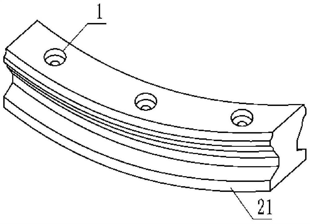
[0003] Due to the limitation of the structure of the circular arc rolling guide, the diameter of the track jacking wire used for radial positioning and adjustment is small, generally figure 1 Half of the height of the positioning surface 21 of the middle track, which makes the radial positioning stiffness and strength of the track low. Under the action of a large radial load, the radial deformation of the track is large, which affects the rotation accuracy
In order to improve the rigidity and positioning accuracy, it is generally necessary to use a guide rail with a larger cross-sectional size, but this will increase the structural size and cost of the slewing mechanism

Method used


Image

  • Radial positioning mechanism and radial position adjusting method of arc rolling guide rail
  • Radial positioning mechanism and radial position adjusting method of arc rolling guide rail
  • Radial positioning mechanism and radial position adjusting method of arc rolling guide rail

Examples


Embodiment Construction

[0028] In order to enable those skilled in the art to better understand the solutions of the present invention, the following will clearly and completely describe the technical solutions in the embodiments of the present invention in conjunction with the drawings in the embodiments of the present invention. Obviously, the described embodiments are only It is an embodiment of a part of the present invention, but not all embodiments. Based on the embodiments of the present invention, all other embodiments obtained by persons of ordinary skill in the art without making creative efforts shall fall within the protection scope of the present invention.

[0029] It should be noted that the terms "first" and "second" in the description and claims of the present invention and the above drawings are used to distinguish similar objects, but not necessarily used to describe a specific sequence or sequence. It is to be understood that the data so used are interchangeable under appropriate ...


PUM


Abstract

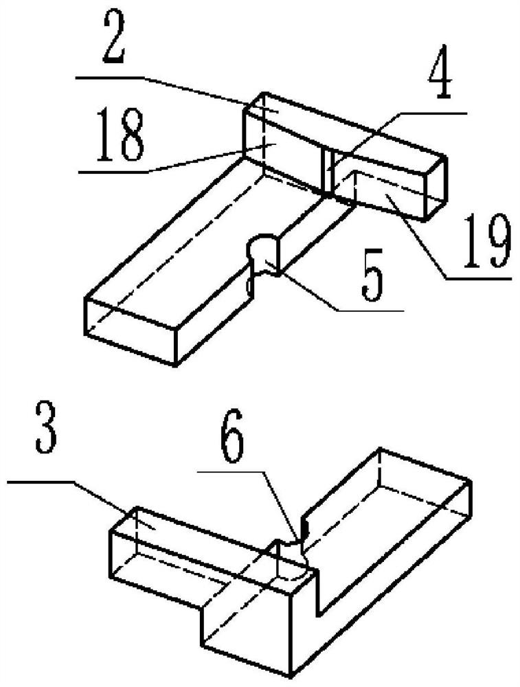
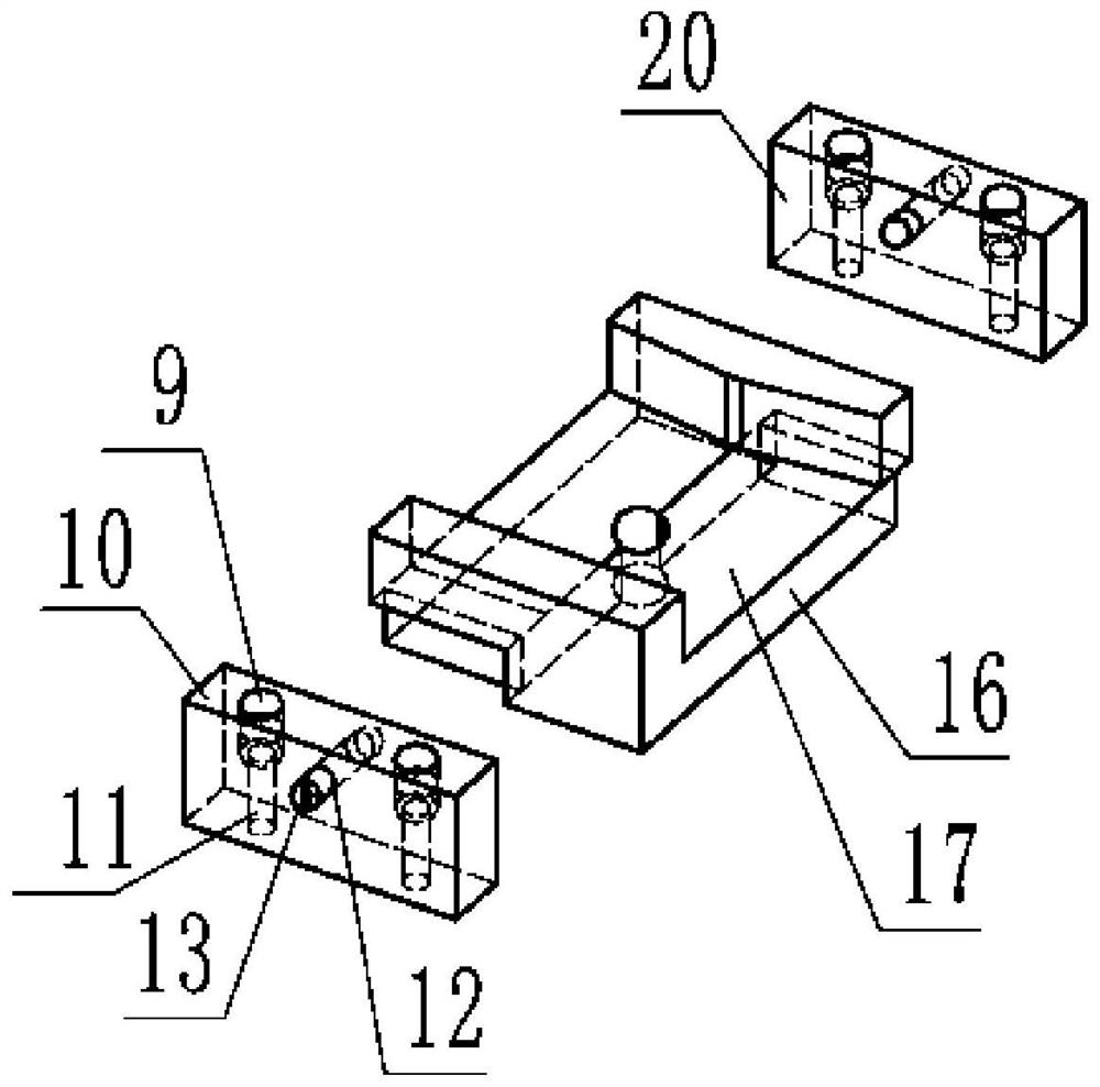
The invention discloses a radial positioning mechanism and a radial position adjusting method of an arc rolling guide rail, and belongs to the field of arc rolling guide rail structures. The radial positioning mechanism comprises an inner-side adjusting block and an outer-side adjusting block, an inner-side sliding block is arranged at the bottom of the inner-side adjusting block, an outer-side sliding block is arranged at the bottom of the outer-side adjusting block, and the inner-side sliding block and the outer-side sliding block are arranged in a mounting groove of the arc rolling guide rail; the inner-side adjusting block and the outer- side adjusting block are used for clamping the track positioning surface of the arc rolling guide rail; an inner-side positioning block is arranged on the outer side of the inner-side adjusting block, and an outer-side positioning block is arranged on the outer side of the outer-side adjusting block; and jackscrew holes for allowing jackscrews to penetrate through are formed in the inner-side positioning block and the outer- side positioning block. The jackscrew of the inner-side positioning block abuts against the inner-side adjusting block, the inner-side adjusting block is tightly attached to the inner side face of the arc rolling guide rail, the jackscrew of the outer-side positioning block abuts against the outer-side adjusting block, and the outer-side adjusting block is tightly attached to the outer side face of the arc rolling guide rail.

Description

technical field [0001] The invention belongs to the structural field of arc rolling guide rails, and relates to a radial positioning mechanism and a radial position adjustment method of arc rolling guide rails. Background technique [0002] The arc rolling guide is a new type of rolling guide. The track of the guide is arc-shaped. The slider on the track can move along the arc. Multiple arc tracks are spliced ​​into a circle. The slider on the track can realize complete circular motion. The arc-shaped track needs to be on the same circle during splicing, so the radial position of each section of the track needs to be adjusted during installation. [0003] Due to the limitation of the structure of the circular arc rolling guide, the diameter of the track jacking wire used for radial positioning and adjustment is small, generally figure 1 Half of the height of the middle track positioning surface 21, which makes the radial positioning stiffness and strength of the track lowe...

Claims


Application Information

Patent Timeline
IPC IPC(8): F16C32/00
CPCF16C32/00
Inventor 王世军韩子锐赵金娟
Owner XIAN UNIV OF TECH
Learn More