Movable jacking pipe retaining support device and retaining method

A bracket device and mobile technology, applied in the direction of pipeline laying and maintenance, pipes/pipe joints/pipes, mechanical equipment, etc., can solve the problems of cumbersome welding, unreliable connection stability of chain hoists, time-consuming and labor-intensive, etc.

Active Publication Date: 2021-09-10
CHINA RAILWAY SHANGHAI ENGINEERING BUREAU GROUP CO LTD +2
View PDF9 Cites 1 Cited by
  • Summary
  • Abstract
  • Description
  • Claims
  • Application Information

AI Technical Summary

Problems solved by technology

The existing anti-retraction devices or methods mainly include the following types: ①A pre-embedded steel plate is installed on the pipe joint, and the pre-embedded steel plate is welded to the guide rail by welding when the pipe joint retreats, and the pipe joint is then cut off after splicing. The disadvantage is that the welding is more cumbersome And it is not reliable, and time-consuming and labor-intensive; ② Use shear pins or support rods to act on the pipe joint to prevent it from continuing to retreat. The disadvantage is that the anti-retreat effect is limited and cannot meet the strength and stability requirements; One end of the connecting pipe joint is connected to the well wall or guide rail to avoid the pipe joint from retreating. The disadvantage is that the chain hoist connection is not reliable, the installation process is cumbersome, and the special back-stop pin hole is set to easily concentrate the stress in some areas of the pipe joint.

Method used


Image

  • Movable jacking pipe retaining support device and retaining method
  • Movable jacking pipe retaining support device and retaining method
  • Movable jacking pipe retaining support device and retaining method

Examples


Embodiment Construction

[0045] The present invention can be better understood from the following examples.

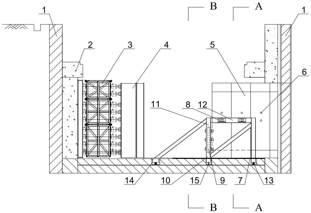
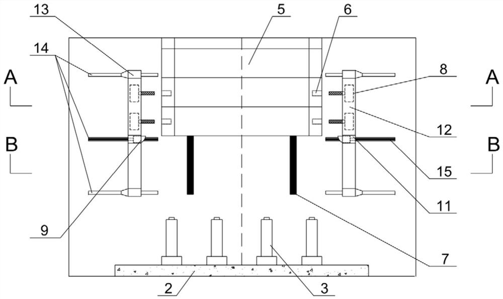
[0046] figure 1 The schematic diagram of the elevation of the anti-retraction bracket device in use is shown. The main structure in the originating shaft includes the working well 1, the back wall 2, the jacking cylinder 3, the jacking iron 4 and the pipe joint guide rail 7, and the pipe joint 5 is equipped with a cylindrical tubular hoisting hole 6 at the position of the upper middle side wall. The mobile pipe jacking anti-retraction support device includes a pair of anti-retraction supports 10 respectively arranged on both sides of the jacking direction of the pipe section 5, and a support guide rail 15 for the anti-retraction support 10 to move along the direction perpendicular to the jacking direction of the pipe section 5;

[0047] On the inner side of the rear end of the anti-retraction brackets 10 on both sides, there are respectively provided with mechanical locking devices 9 for rest...


PUM


Abstract

The invention discloses a movable jacking pipe retaining support device and a retaining method. The movable jacking pipe retaining support device comprises a pair of retaining supports arranged on the two sides of the jacking direction of a pipe joint correspondingly and a support guide rail used for enabling the retaining supports to move in the direction perpendicular to the jacking direction of the pipe joint. The inner sides of the rear ends of the retaining supports on the two sides are each provided with a mechanical locking and clamping device used for limiting backward retreating of the pipe joint. Movable hydraulic telescopic rod devices used for being clamped into the side wall of the pipe joint are arranged on the inner sides of the top ends of the retaining supports on the two sides correspondingly. When the pipe joint advances in the jacking direction, the pipe joint firstly makes contact with and compresses the mechanical locking and clamping devices on the two sides, and after the whole pipe joint passes, the mechanical locking and clamping devices rebound and abut against the rear end of the pipe joint to limit backward retreating of the pipe joint; and meanwhile, the movable hydraulic telescopic rod devices can move to the positions of hoisting holes reserved in the side wall of the pipe joint, and pin shafts are inserted into the hoisting holes, so that the pipe joint is stopped and limited.

Description

technical field [0001] The invention relates to a mobile pipe jacking anti-retraction bracket device and a method for anti-retreating, belonging to the field of non-excavation pipe jacking engineering construction. Background technique [0002] Pipe jacking technology is a kind of non-excavation technology. Its basic principle is that with the help of the jacking force of the main jacking cylinder, the pipe jacking machine continuously cuts the front soil layer, and discharges the soil body through the excavation device, and the rear pipe joints continue to move toward the ground. Push forward until the pipe jacking section runs through. However, there must be hoisting and splicing of pipe joints during the construction process. At this time, the jacking oil cylinder and the jacking iron are separated from the pipe joints, and because the head-on resistance of the pipe jacking machine is greater than the frictional resistance around the pipe, the pipe jacking pipeline has an...

Claims


Application Information

Patent Timeline
IPC IPC(8): F16L1/036F16L1/06F16L1/09
CPCF16L1/036F16L1/06F16L1/09
Inventor 戢鸿鑫刘跃军周浩陈雪华项侨陈清树林振镇贾鹏蛟罗桑倪芃芃覃小纲
Owner CHINA RAILWAY SHANGHAI ENGINEERING BUREAU GROUP CO LTD
Why Eureka
Try Eureka