Eureka AIR delivers breakthrough ideas for toughest innovation challenges, trusted by R&D personnel around the world.

Optical system, camera module and electronic equipment

An optical system and optical axis technology, which is applied in the fields of optical systems, camera modules and electronic equipment, can solve the problems that the size of the effective pixel area of ​​the lens is difficult to take into account at the same time, and the shooting effect is not good.

Inactive Publication Date: 2021-09-10
JIANGXI JINGCHAO OPTICAL CO LTD
View PDF0 Cites 0 Cited by
  • Summary
  • Abstract
  • Description
  • Claims
  • Application Information

AI Technical Summary

Problems solved by technology

[0004] The surface shape of each lens, the aperture of the lens, and the size of the effective pixel area of ​​the photosensitive element in the previous seven-chip optical system are difficult to take into account at the same time, resulting in poor shooting results

Method used


Image

  • Optical system, camera module and electronic equipment
  • Optical system, camera module and electronic equipment
  • Optical system, camera module and electronic equipment

Examples


no. 1 example

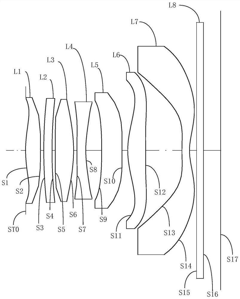
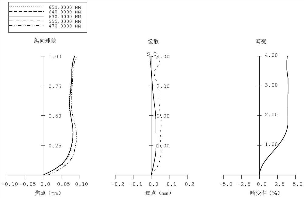
[0056] Please refer to Figure 1a and Figure 1b , the optical system of this embodiment, from the object side to the image side, includes:

[0057] The first lens L1 has a positive refractive power. The object side S1 of the first lens L1 is convex at the optical axis and concave at the circumference; the image side S2 of the first lens L1 is convex at the optical axis and at the circumference;

[0058] The second lens L2 has a negative refractive power, and the object side S3 of the second lens L2 is convex at the optical axis and at the circumference; the image side S4 of the second lens L2 is concave at the optical axis and at the circumference;

[0059] The third lens L3 has positive refractive power. The object side S15 of the third lens L3 is concave at the optical axis and convex at the circumference; the image side S6 of the third lens L3 is convex at the optical axis and at the circumference. ;

[0060] The fourth lens L4 has negative refractive power. The object s...

no. 2 example

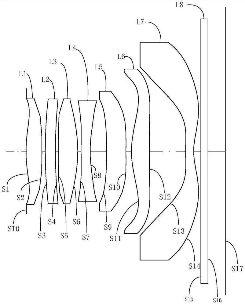
[0077] Please refer to Figure 2a and Figure 2b , the optical system of this embodiment, from the object side to the image side, includes:

[0078] The first lens L1 has positive refractive power. The object side S1 of the first lens L1 is convex at the optical axis and concave at the circumference; the image side S2 of the first lens L1 is convex at the optical axis and at the circumference. ;

[0079] The second lens L2 has a positive refractive power, and the object side S3 of the second lens L2 is convex at the optical axis and at the circumference; the image side S4 of the second lens L2 is concave at the optical axis and at the circumference;

[0080] The third lens L3 has a positive refractive power. The object side S5 of the third lens L3 is concave at the optical axis and convex at the circumference, and the image side S6 of the third lens L3 is convex at the optical axis and at the circumference. ;

[0081] The fourth lens L4 has negative refractive power. The o...

no. 3 example

[0095] Please refer to Figure 3a and Figure 3b , the optical system of this embodiment, from the object side to the image side, includes:

[0096] The first lens L1 has a positive refractive power. The object side S1 of the first lens L1 is convex at the optical axis and concave at the circumference; the image side S2 of the first lens L1 is concave at the optical axis and is concave at the circumference. Convex;

[0097] The second lens L2 has a positive refractive power, and the object side S3 of the second lens L2 is convex at the optical axis and at the circumference; the image side S4 of the second lens L2 is concave at the optical axis and at the circumference;

[0098] The third lens L3 has positive refractive power. The object side S5 of the third lens L3 is concave at the optical axis and convex at the circumference; the image side S6 of the third lens L3 is convex at the optical axis and at the circumference. ;

[0099] The fourth lens L4 has negative refractiv...


PUM


Abstract

The invention provides an optical system, a camera module and an electronic device. The optical system sequentially comprises a first lens, a second lens, a third lens, a fourth lens, a fifth lens, a sixth lens and a seventh lens from an object side to an image side, wherein the first lens element has positive refractive power, and the object-side surface of the first lens is a convex surface at an optical axis; the object-side surface of the second lens is a convex surface at the optical axis, and the image-side surface is a concave surface; the third lens has positive refractive power, the object-side surface of the third lens is a concave object at the optical axis, and the image-side surface is a convex surface; the fourth lens has negative refractive power, the object-side surface of the fourth lens is a convex surface at the optical axis, and the image-side surface is a concave image surface; the fifth lens has negative refractive power, and the object-side and image-side surfaces of the fifth lens are concave surfaces at the optical axis; the sixth lens element has positive refractive power, and the object-side surface of the sixth lens is a convex surface at the optical axis; the seventh lens has negative refractive power, the object-side surface of the seventh lens is a convex surface at the optical axis, and the image-side surface is a concave surface at the optical axis; and the optical system satisfies the following conditional expression: 0.5 < CDL1 / Imgh < 0.8. Through the arrangement, the optical system has proper light passing quantity, so that the definition of a shot image is ensured.

Description

technical field [0001] The invention belongs to the technical field of optical imaging, and in particular relates to an optical system, a camera module and electronic equipment. Background technique [0002] With the wide application of mobile phones, tablet computers, drones, computers, cameras and other electronic products in daily life, various technological improvements have been introduced. Among them, the improvement and innovation of the shooting effect of electronic products has become the focus of attention. [0003] Light flux is an important parameter in the optical system, which refers to the amount of light entering per unit time, which directly affects the shooting effect of electronic products. Too high or insufficient light flux will have a negative impact on the shooting picture. The amount of light passing through is related to the aperture of the optical system and the size of the photosensitive surface. The larger the aperture of the optical system, the ...

Claims


Application Information

Patent Timeline
Patent Type & Authority Applications(China)
IPC IPC(8): G02B13/00G02B13/18
CPCG02B13/0045G02B13/18
Inventor 杨健张文燕刘彬彬李明邹海荣
Owner JIANGXI JINGCHAO OPTICAL CO LTD
Why Eureka
Eureka Blog
Learn More