High-voltage contactor

A technology of high-voltage contactors and high-voltage contacts, which is applied in the direction of relays, electromagnetic relays, details of electromagnetic relays, etc.

Pending Publication Date: 2021-09-10
VOLKSWAGEN AG
View PDF1 Cites 2 Cited by
  • Summary
  • Abstract
  • Description
  • Claims
  • Application Information

AI Technical Summary

Problems solved by technology

Problems in suspension can lead to contact bonding due to arcing

Method used


Image

  • High-voltage contactor
  • High-voltage contactor
  • High-voltage contactor

Examples


Embodiment Construction

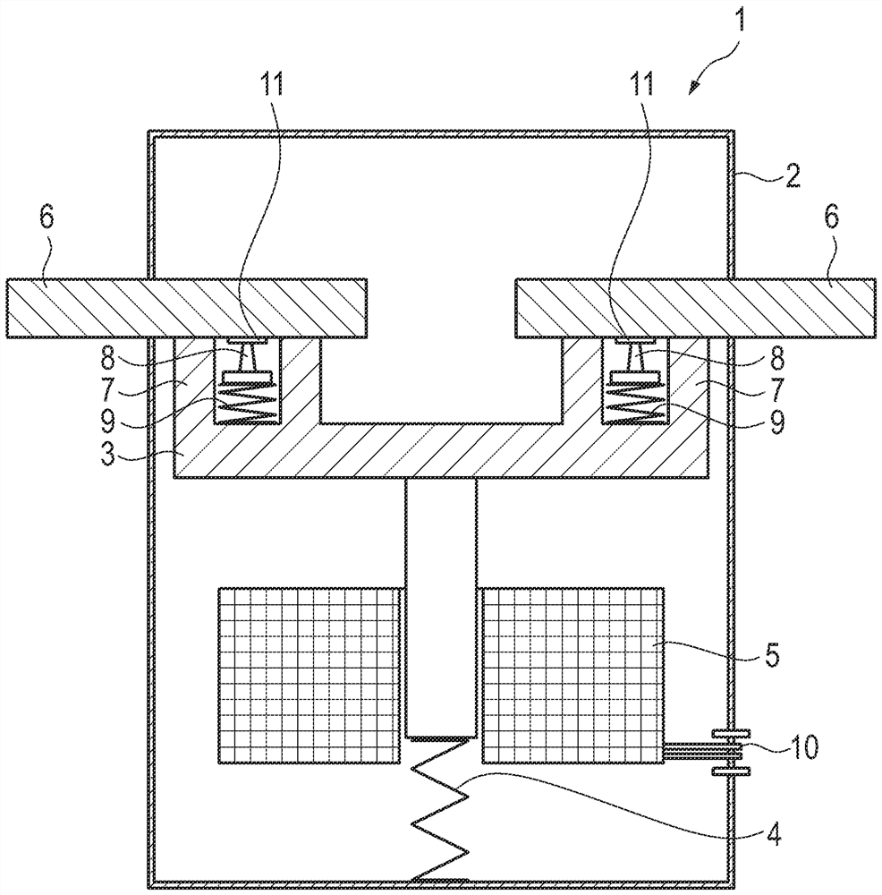
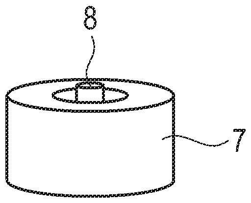
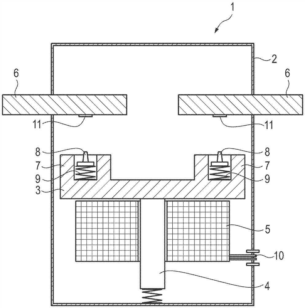
[0019] The high-voltage contactor 1 comprises a housing 2 , a contact bridge 3 , an armature 4 , a coil 5 , two high-voltage contacts 6 , two main contacts 7 and two auxiliary contacts 8 , which are supported on springs 9 . The coil 5 has electrical connections 10 leading out of the housing 2 . The armature 4 is supported elastically. With the spring 9 unloaded, the auxiliary contact 8 protrudes beyond the main contact 7 . Furthermore, the high-voltage contact 6 has a protrusion 11 in each case in the contact region of the auxiliary contact 8 . The auxiliary contact 8 is concentrically surrounded by its main contact 7 , wherein the main contact 7 is of cylindrical design (see figure 2 ). If the high-voltage contactor 1 is now switched from the rest position into the on position by energizing the connection 10 , the armature 4 and the contact bridge 3 are moved upwards. Due to the fact that the auxiliary contacts 8 protrude beyond the main contacts 7 , these two auxiliary ...


PUM


Abstract

The invention relates to a high-voltage contactor (1), comprising a contact bridge (3) with two main contacts (7), two high-voltage contacts (6) and an armature (4), the high-voltage contactor (1) being designed in such a way that the main contacts (7) are separated from the high-voltage contacts (6) in static positions and in on positions, the main contact (7) contact the respective high-voltage contacts (6) so that the high-voltage contacts (6) are electrically connected via the contact bridge (3), each main contact (7) being associated with an auxiliary contact (8), the auxiliary contacts (8) being electrically connected to the contact bridge (3), the auxiliary contacts (8) being resiliently mounted, the auxiliary contacts (8) having a greater electrical resistance than the main contacts (7), the high-voltage contactor (1) being designed in such a way that when the main contacts (7) are separated from the high-voltage contacts (6), the auxiliary contacts (8) remain connected to the high-voltage contacts (6) or disconnect from the high-voltage contacts (6) relative to the main contacts (7) in a time-delayed manner.

Description

technical field [0001] The invention relates to a high-voltage contactor, in particular for a traction network of an electric or hybrid vehicle. Background technique [0002] Conducting and switching currents up to the kiloampere range at DC voltages of 400 V and higher and reliably disconnecting overcurrents in the event of a fault (Ueberstrom) belong to the functions of high-voltage contactors in the range of electric vehicles (Elektromobilitaet). . A problem in high-voltage contactors is so-called levitation, ie the opening of the contacts due to the current flowing through them. The resulting suspension force counteracts the contact closure force here. Repulsion results from this, ie the contacts do not make contact over the entire surface, but the current has to flow through point-shaped constrictions. Opposite current directions then create mutually repelling magnetic fields. Problems in suspension can lead to contact bonding due to arcing. [0003] From DE 10 201...

Claims


Application Information

Patent Timeline
Patent Type & Authority Applications(China)
IPC IPC(8): H01H50/54H01H9/38H01H9/44H01H9/34
CPCH01H50/541H01H9/38H01H9/44H01H9/34H01H9/36H01H9/443H01H50/546H01H9/42H01H3/001
Inventor P·林德
Owner VOLKSWAGEN AG
Why Eureka
Try Eureka