High-temperature-resistant dustproof chuck device

A high-temperature-resistant, chucking technology, used in chucks, auxiliary devices, accessories of tool holders, etc., to solve the problems that movable jaws are difficult to move, cannot move, and have different expansions.

Active Publication Date: 2021-09-14
MATERIAL INST OF CHINA ACADEMY OF ENG PHYSICS
View PDF6 Cites 0 Cited by
  • Summary
  • Abstract
  • Description
  • Claims
  • Application Information

AI Technical Summary

Problems solved by technology

[0003] In the prior art, after a period of continuous spraying operation, the heat energy generated during the spraying operation is conducted to the chuck. Due to the different distances from the heat conduction to different parts of the chuck, the temperature rise and expansion of different parts of

Method used


Image

  • High-temperature-resistant dustproof chuck device
  • High-temperature-resistant dustproof chuck device
  • High-temperature-resistant dustproof chuck device

Examples


Embodiment Construction

[0032] In order to make the purposes, technical solutions and advantages of the embodiments of the present invention clearer, the technical solutions in the embodiments of the present invention will be clearly and completely described below in conjunction with the embodiments of the present invention. Obviously, the described embodiments are part of the implementation of the present invention. way, not all implementations. Based on the embodiments of the present invention, all other embodiments obtained by persons of ordinary skill in the art without creative efforts shall fall within the protection scope of the present invention. Thus, the detailed descriptions of embodiments of the invention provided below are not intended to limit the scope of the invention as claimed, but are merely representative of selected embodiments of the invention.

[0033] In the description of the present invention, it should be understood that the terms indicating the orientation or positional re...


PUM


Abstract

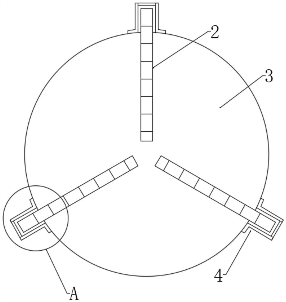
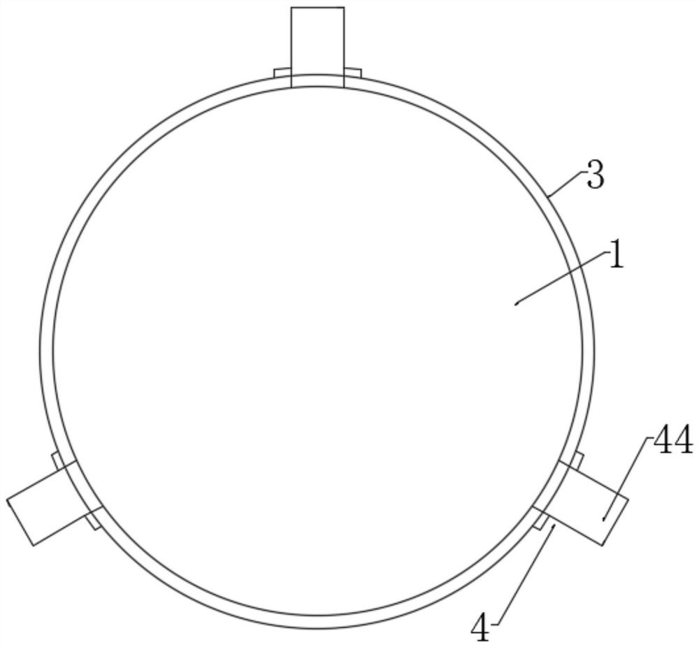
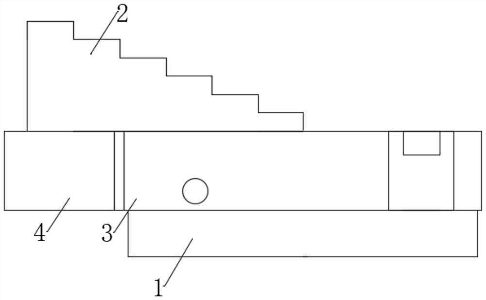
The invention relates to the technical field of surface engineering, and particularly discloses a high-temperature-resistant dustproof chuck device. The device comprises a chuck body, clamping jaws installed on the chuck body, a dustproof cover arranged on the chuck body in a sleeving mode and coaxial with the chuck body, and shielding covers installed on the outer side of the dustproof cover and communicating with the interior of the dustproof cover; the dustproof cover is provided with a groove used for installing the chuck body, and a gap exists between the bottom of the groove and the upper surface of the chuck body; and the shielding covers and the clamping jaws are arranged in a one-to-one correspondence mode. According to the device, dust can be prevented from entering gaps between the clamping jaws and the chuck body, and the device is resistant to high temperature.

Description

technical field [0001] The invention relates to the technical field of surface engineering, and more particularly, to a high temperature resistant dustproof chuck device. Background technique [0002] Plasma spraying, flame spraying, supersonic spraying and other high temperature spraying and cold spraying are a kind of important surface modification methods of materials. The chuck is a mechanical device used to clamp the workpiece during the spraying process. It uses the radial movement of the movable jaws evenly distributed on the chuck body to clamp and position the sprayed workpiece. [0003] In the prior art, after the continuous spraying operation for a period of time, the heat energy generated during the spraying operation is conducted to the chuck. Due to the different distances from the heat conduction to different parts of the chuck, different parts of the chuck have different temperature rises and different expansions. The movable jaws of the disc are difficult t...

Claims


Application Information

Patent Timeline
IPC IPC(8): B23B31/02B23B25/04
CPCB23B31/02B23B25/04
Inventor 肖云锋汪敏熊雪峰魏钢余良波
Owner MATERIAL INST OF CHINA ACADEMY OF ENG PHYSICS
Why Eureka
Try Eureka