Laser cutting machine and deslagging method thereof

A laser cutting machine and laser cutting head technology, applied in laser welding equipment, metal processing equipment, welding equipment, etc., can solve the problems of general chip removal effect of chip remover, small pipe diameter, and reduced pipe processing quality.

Active Publication Date: 2021-09-14
FOSHAN LONGXIN LASER TECH CO LTD
View PDF5 Cites 0 Cited by
  • Summary
  • Abstract
  • Description
  • Claims
  • Application Information

AI Technical Summary

Problems solved by technology

[0005] However, since the outer diameter of the chip removal pipe must be smaller than the inner diameter of the metal pipe, the pipe diameter is small, the air flow rate is fast, and the resistance is large (that is, the pressure drop is large), and it is not easy to achieve the ideal vacuum degree in the chip removal pipe. Chips have to be sucked into the chip removal pipe through the small gap at the top of the chip removal pipe, therefore, the chip removal effect of the chip removal positioner is mediocre and the processing quality of the pipe is reduced

Method used


Image

  • Laser cutting machine and deslagging method thereof
  • Laser cutting machine and deslagging method thereof
  • Laser cutting machine and deslagging method thereof

Examples


Embodiment Construction

[0031] This part will describe the specific embodiment of the present invention in detail, and the preferred embodiment of the present invention is shown in the accompanying drawings. Each technical feature and overall technical solution of the invention, but it should not be understood as a limitation on the protection scope of the present invention.

[0032] In the description of the present invention, it should be understood that the orientation descriptions, such as up, down, front, back, left, right, etc. indicated orientations or positional relationships are based on the orientations or positional relationships shown in the drawings, and are only In order to facilitate the description of the present invention and simplify the description, it does not indicate or imply that the device or element referred to must have a specific orientation, be constructed and operated in a specific orientation, and thus should not be construed as limiting the present invention.

[0033] I...


PUM


Abstract

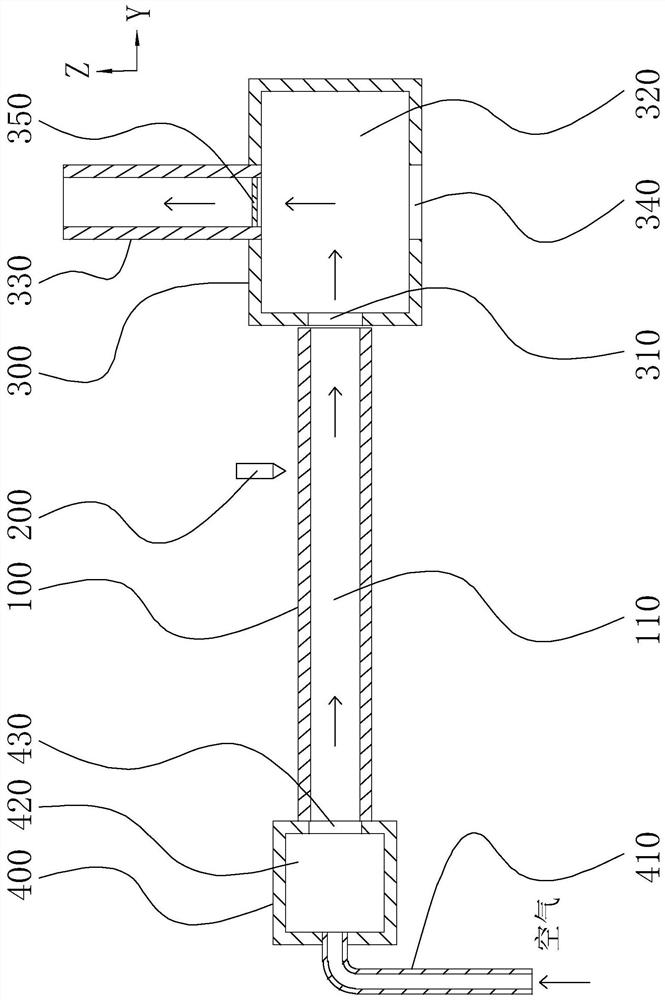
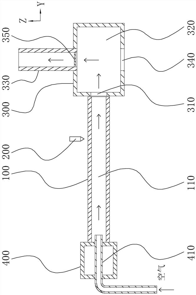
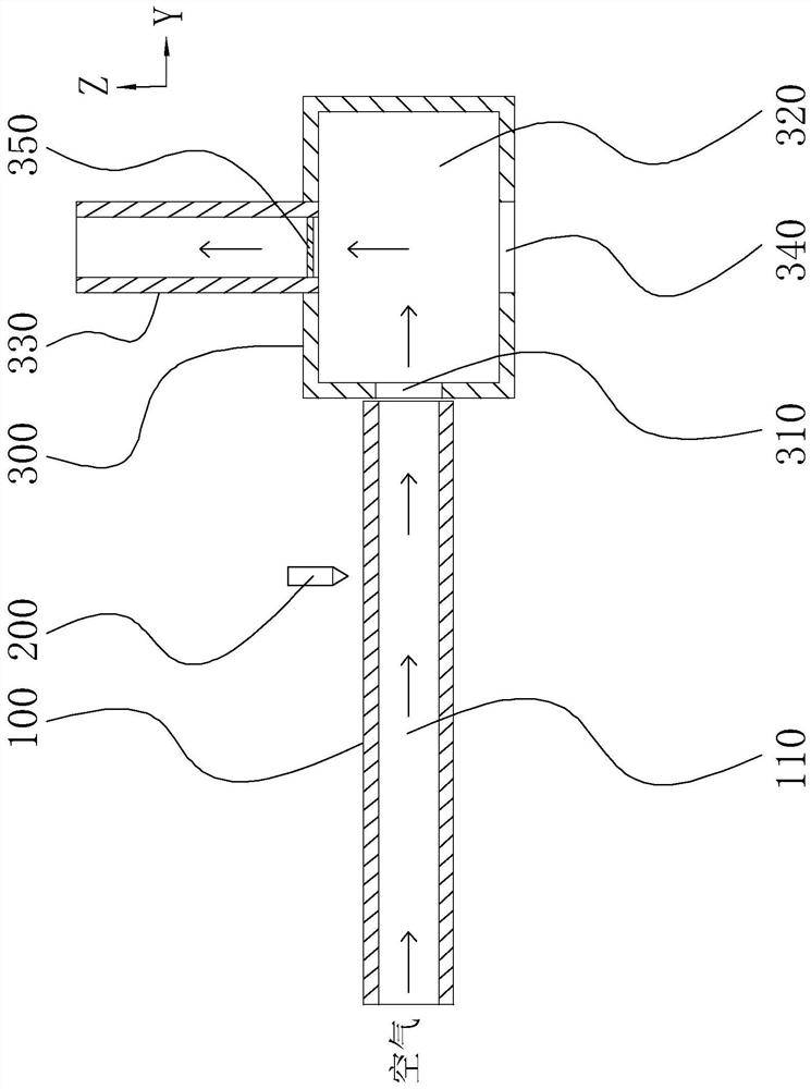
The invention discloses a laser cutting machine. The laser cutting machine comprises a fixed chuck, a laser cutting head located on the right side of the fixed chuck, a movable chuck located on the left side of the fixed chuck, a slag remover located on the right side of the laser cutting head and a gas extractor, wherein the slag remover is provided with an inner cavity, a gas suction inlet and a gas suction pipe, the gas suction inlet is located in the left side face of the slag remover and communicates with the inner cavity, one end of the gas suction pipe communicates with the inner cavity, and the other end is connected to the gas suction device, in addition, the invention further provides a slag removal method which comprises the following steps of starting the gas extractor to extract gas from the inner cavity of the slag remover, and the slag remover is driven to move relative to a metal pipe, so that the gas exhaust inlet of the slag remover communicates with one end of the metal pipe, and gas exhaust is conducted on a pipe cavity of the metal pipe. Compared with a mode that a scrap removing pipe is inserted into the metal pipe to remove scraps, the metal pipe in the cut state serves as a part of the slag remover, the inner diameter of the metal pipe is larger than that of the scrap removing pipe, when the metal pipe is vacuumized, the pipe cavity of the metal pipe can achieve the ideal vacuum degree more easily, and the scrap removing effect can be improved.

Description

technical field [0001] The invention relates to the technical field of pipe cutting machines, in particular to a laser cutting machine and a slag removal method thereof. Background technique [0002] During the laser cutting process, a large amount of metal slag will be blown into the metal pipe, adhere to the inner wall of the metal pipe and form burrs after cooling, which seriously affects the smoothness of the pipe wall surface. When the internal wall surface of the pipe product has high requirements, It is necessary to carry out the deburring process on the pipe, which undoubtedly reduces the benefit of the enterprise in producing the pipe. [0003] At present, in order to complete the slag removal work, a chip removal positioner is often installed on the laser cutting machine. The chip removal positioner mainly includes a plug, a chip removal pipe and a driving device. The through hole corresponding to the pipe, the diameter of the through hole is smaller than the inne...

Claims


Application Information

Patent Timeline
Patent Type & Authority Applications(China)
IPC IPC(8): B23K26/38B23K26/70
CPCB23K26/38B23K26/70B23K26/702Y02P70/10
Inventor 夏国章周德响刘园冯泽远
Owner FOSHAN LONGXIN LASER TECH CO LTD
Why Eureka
Try Eureka