
Engineering geological drilling and exploring equipment

A drilling equipment and engineering geology technology, applied in drilling equipment, drilling tools, earthwork drilling, etc., can solve problems such as deformation, bit damage, and increased friction between the bit and the soil layer.

Pending Publication Date: 2021-09-14
广西华南岩土工程集团有限公司
View PDF0 Cites 0 Cited by
  • Summary
  • Abstract
  • Description
  • Claims
  • Application Information

AI Technical Summary

Problems solved by technology

[0003] Based on the inventors' findings above, the existing engineering geological drilling equipment mainly has the following deficiencies, for example: in arid areas where it does not rain for a long time, when the soil is drilled with a drilling bit, due to the The lack of water will increase the friction between the drill bit and the soil layer, and the drill bit will rotate at a high speed when digging into the rock layer, causing the temperature of the drill bit to rise and deform, resulting in damage to the drill bit

Method used


Image

  • Engineering geological drilling and exploring equipment
  • Engineering geological drilling and exploring equipment
  • Engineering geological drilling and exploring equipment

Examples


Embodiment 1

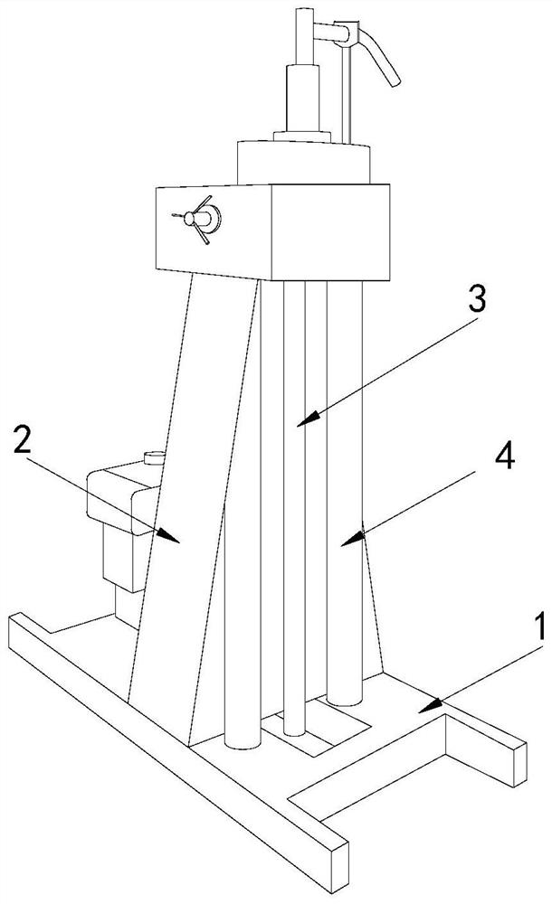
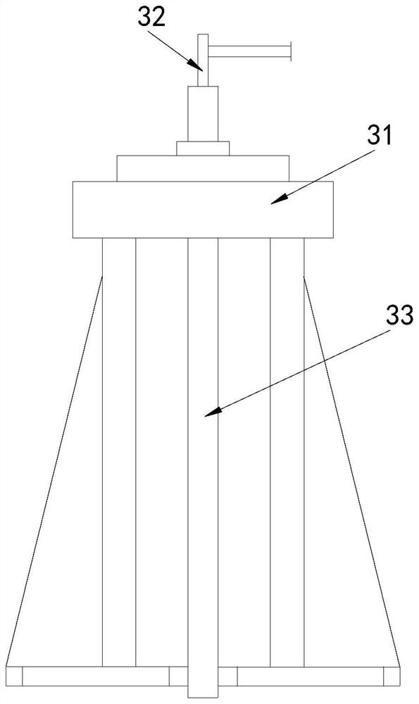
[0028] Example 1: Please refer to Figure 1-Figure 6 , the specific embodiments of the present invention are as follows:

[0029] Its structure comprises support plate 1, support frame 2, main body 3, support column 4, and the top of described support plate 1 is provided with support frame 2, and described main body 3 is installed on the top front end of support frame 2, and described support column 4 is provided with There are two, and they are installed on both sides of the main body 3 respectively. The main body 3 includes a limiting platform 31, a water inlet pipe 32, and drilling equipment 33. The limiting platform 31 is installed on the top of the support frame 2. The inlet The water pipe 32 is installed vertically on the top of the limiting platform 31 , and the drilling equipment 33 passes through the limiting platform 31 and is connected with the water inlet pipe 32 .

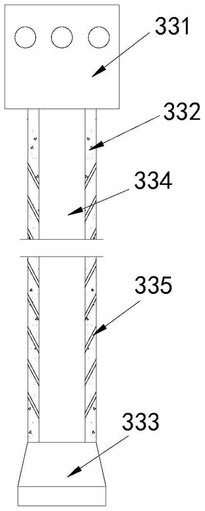
[0030] The drilling equipment 33 includes a mounting seat 331, a drilling pipe 332, a drilling blo...

Embodiment 2

[0035] Example 2: Please refer to Figure 7-Figure 9 , the specific embodiments of the present invention are as follows:

[0036]The friction device a4 includes a friction block c1, a cut groove c2, a water outlet c3, and a friction groove c4. There are eight friction blocks c1 arranged around the bottom end surface of the drill bit a1. The cut groove c2 is set There are eight of them, and they are located between two friction blocks c1. The water outlet c3 is set in the cut groove c2. The friction groove c4 is located on the front and rear end surfaces of the friction block c1. The friction groove c4 is wave-shaped, which is beneficial to The friction force with the soil is improved through the friction groove c4.

[0037] The water outlet hole c3 includes a water storage tank c31, a fine flow hole c32, a water outlet port c33, and a soil retaining block c34. The water storage tank c31 is arranged at the upper end of the cutting groove c2. Arranged on the top end surface of...


PUM


Abstract

The invention discloses engineering geology drilling and exploring equipment which structurally comprises a supporting plate, a supporting frame, a main body and supporting columns. The supporting frame is arranged at the top of the supporting plate, the main body is installed at the front end of the top of the supporting frame, the two supporting columns are installed at the two sides of the main body respectively, and the main body comprises a limiting table, a water inlet pipe and exploring and drilling equipment body; and the exploring and drilling equipment body comprises a mounting base, an exploring and drilling pipe, an exploring and drilling block, an exploring and drilling groove and a water through hole, the exploring and drilling block comprises an exploring and drilling head, a water flowing groove, a water inlet groove and a friction device, the water inlet groove comprises a circulating groove, a water dripping groove and a baffle, and the baffle comprises a plate body, a through hole and a rear end opening. According to the engineering geology drilling and exploring equipment, the water through hole is used for guiding water flow outside the exploring and drilling pipe towards the exploring and drilling groove in the interior, and then the water flow is guided to the bottom end face of the exploring and drilling block through the exploring and drilling groove, so that the exploring and drilling block can be in full contact with water for cooling during exploring and drilling, and the situation that the exploring and drilling block is damaged due to too high temperature caused by friction is prevented.

Description

technical field [0001] The invention relates to the technical field of geological drilling equipment, in particular to engineering geological drilling equipment. Background technique [0002] The purpose of engineering geology is to find out the geological conditions of various engineering sites, conduct a comprehensive evaluation of the site and its related geological problems, analyze and predict the possible changes and effects of geological conditions under the action of engineering buildings, Select the optimal site, and propose engineering measures to solve unfavorable geological problems, and provide reliable scientific basis for ensuring the reasonable design, smooth construction and normal use of the project. Drilling bits are required in the exploration process of engineering geology. [0003] Based on the inventors' findings above, the existing engineering geological drilling equipment mainly has the following deficiencies, for example: in arid areas where it does...

Claims


Application Information

Patent Timeline
Patent Type & Authority Applications(China)
IPC IPC(8): E21B15/00E21B21/00E21B12/00
CPCE21B15/00E21B21/00E21B12/00
Inventor 梁清潭左述明蒙霞
Owner 广西华南岩土工程集团有限公司
Learn More