Mounting device for field unit

A field device, fastening device technology, applied in the direction of measurement device, antenna support/installation device, utilization of re-radiation, etc., can solve the problem of unspecified antenna connection, etc.

Pending Publication Date: 2021-09-14
VEGA GRIESHABER GMBH & CO
View PDF0 Cites 0 Cited by
  • Summary
  • Abstract
  • Description
  • Claims
  • Application Information

AI Technical Summary

Problems solved by technology

Additionally, the antenna must be connected to the sensor using a cable
However, the corresponding antenna connection is usually not specified on autonomous field devices

Method used


Image

  • Mounting device for field unit
  • Mounting device for field unit
  • Mounting device for field unit

Examples


Embodiment Construction

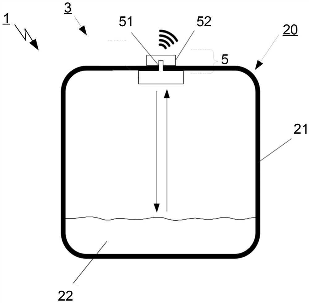
[0049] figure 1 Shown is a metering device 1 according to the present application for filling level measurement in a metal tank with an autonomous field device 3 formed as a filling level metering device.

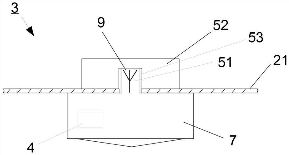
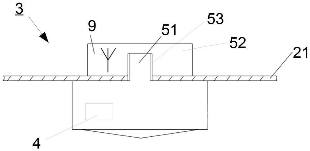
[0050] In the present embodiment, the autonomous level metering device 3 is formed as a radar level metering device and measures the level of the medium 22 in the container 20 . In the wall 21 of the container 20 is formed a hole in which the autonomous level metering device 3 is held using fastening means 5 . To this end, the fastening device 5 has a first sensor-side part 51 which is arranged in the container 20 together with at least a radar sensor for fill level measurement.

[0051] The fill level sensor is arranged in a cylindrical housing 7 which is integrally formed with the first part 51 of the fastening device 5 . In order to form the mechanical interface, the first part 51 of the fastening means has a cylindrical bolt-like extension which is arranged in the hol...


PUM


Abstract

An autonomous field device for process automation, having a sensor, a wireless module, and a fastening device to fasten the field device on a wall. The invention is characterized in that, the fastening device has at least a two-part design and is formed such that a first, sensor-side part of the fastening device can be installed from a first side of the wall and a second part of the fastening device can be installed from a second side of the wall, wherein the parts of the fastening device form a mechanical first interface penetrating the wall in order to fasten the field device on the wall.

Description

technical field [0001] The invention relates to a fastening device for a field device for process automation according to the preamble of claim 1 . Background technique [0002] Various fastening devices for field devices are known in the prior art. In many cases, standardized process connections are used to secure field devices in the metrology environment. [0003] A process connection is defined as the mechanical interface used to arrange field devices or sensors in a process environment. Known process connections include various screw connections and flanges, by means of which field devices can be arranged in the process environment. For this purpose, field devices are for example screwed into the walls of containers, such as tanks, silos or pipe assemblies, or joined to flanges connected to these containers. [0004] In this case, the term "field device" encompasses all kinds of technical equipment directly related to the production process. In this case, "site" ref...

Claims


Application Information

Patent Timeline
Patent Type & Authority Applications(China)
IPC IPC(8): F16B19/10H01Q1/22
CPCF16B19/10H01Q1/22G01D11/30G01D21/00G01F23/284G01S13/88H01Q1/225H01Q1/2291H01Q21/28G01L19/086H04W4/38G01F23/22H01Q1/1214
Inventor 弗洛里安·克莱默帕特里克·海茨曼斯特凡·奥尔盖尔
Owner VEGA GRIESHABER GMBH & CO
Why Eureka
Try Eureka