
Motherboard of computer

A technology for motherboards and computers, applied in the direction of printed circuit board sockets, structural connections of printed circuits, circuits, etc., which can solve problems such as increasing the space of slots

Inactive Publication Date: 2004-01-07
UNKNOWN +1
View PDF2 Cites 0 Cited by
  • Summary
  • Abstract
  • Description
  • Claims
  • Application Information

AI Technical Summary

Problems solved by technology

It can only be solved by increasing the space of the slot

Method used

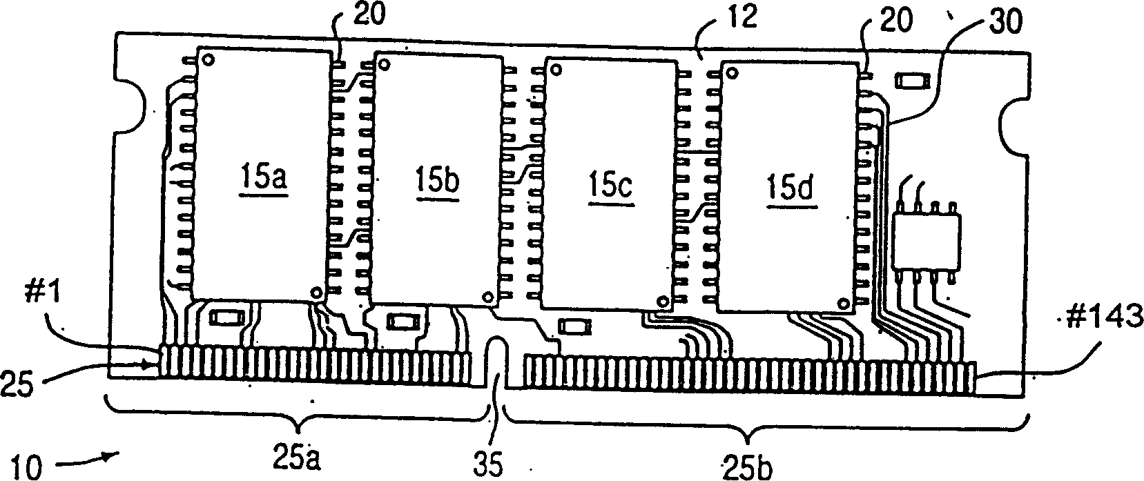
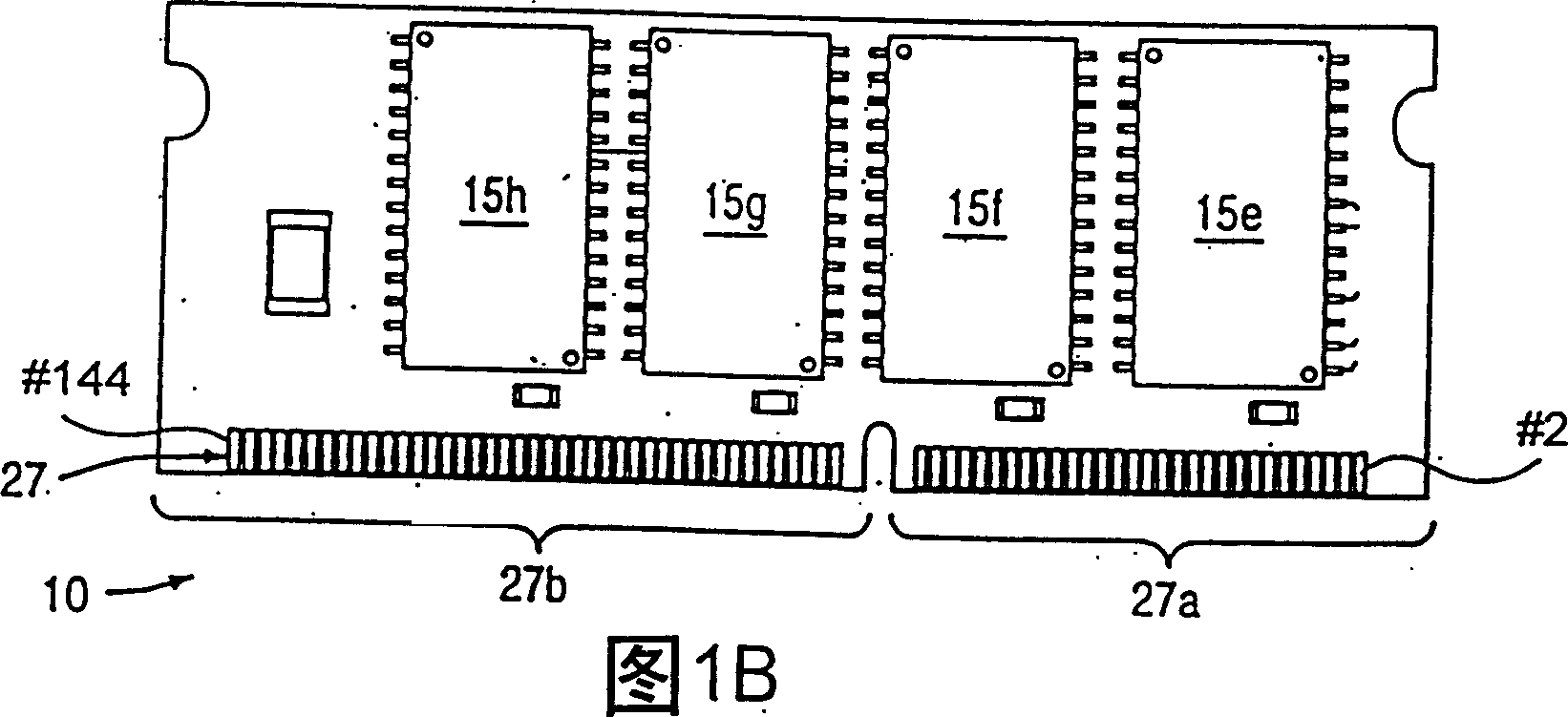
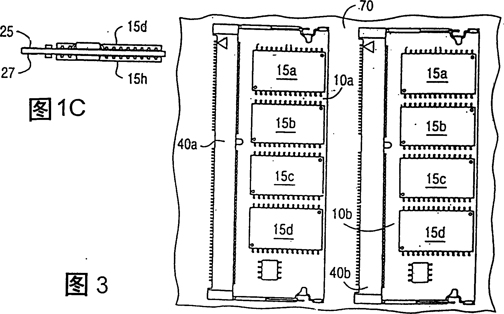

Image

  • Motherboard of computer
  • Motherboard of computer
  • Motherboard of computer

Examples


Embodiment Construction

[0052] As shown in FIGS. 4A, 4B, 4C and 4D, they respectively represent a top view, a bottom view, a module receiving side view and a rear view of a DIMM slot 40' according to an embodiment of the present invention. Wherein, socket 40' is used for one of a complementary pair, and the other of this complementary pair adopts conventional socket 40.

[0053] Socket 40' includes socket body 45' formed with module receiving recess 47', module latches 50a' and 50b'. As in the prior art, an asymmetric separation point 55' on the module receiving side of the socket body effectively divides the groove into short and long sections, represented at 47a' and 47b'.

[0054] Socket 40' includes a set of upper contacts 60' and a set of lower contacts 62'. The upper contacts include a set of first terminals located on the upper surface of the module receiving recess 47', and a set of second terminals located on the lower surface of the socket and extending away from the backside. The lower c...


PUM


Abstract

An improved motherboard layout uses DIMM sockets in complementary pairs where the sockets have keys are in opposite locations. In essence, the first and second sockets in a pair are mirror images of each other. The sockets can be configured for single DIMMs (single-decker) or can be configured in a double-decker configuration. In circuit board layouts where both sockets are mounted on the same side of the motherboard, the sockets are disposed with their module-receiving recesses facing toward or away from each other, rather than in the same direction as in the prior art configuration. The complementary sockets can be disposed on opposite sides of the motherboard. In this type of layout, the respective keys are immediately opposite each other.

Description

technical field [0001] The invention relates to a motherboard of a computer, in particular to a motherboard of a computer which is convenient for fixing Dual In-Line Memory Modules (DIMMs). Background technique [0002] In computer systems (including personal computers and workstations), system memory generally adopts industry standard memory modules. A memory module for system memory consisting of multiple dynamic random access memory (DRAM) chips mounted on a small circuit board with electrical edge contacts that engage sockets on the motherboard . [0003] Recent industry standard modules include Single In-Line Memory Modules (SIMMs) and Dual In-Line Memory Modules. The single in-line memory module is arranged on one side of the circuit board, and the dual in-line memory module is arranged on two sides of the circuit board. There are also memory modules that act as caches, using faster static random access memory (SRAM) chips instead of dynamic random access memory (DR...

Claims


Application Information

Patent Timeline
Patent Type & Authority Patents(China)
IPC IPC(8): G11C5/00H01R12/71H01R12/83H05K1/14H05K3/36H05K7/14
CPCH05K2203/1572H01R12/716H05K1/141H01R23/682H01R12/83H05K7/1431H05K1/144H05K2201/10189H05K3/368H05K2201/10159
Inventor 许棠隆杰生·思·金
Owner UNKNOWN
Learn More